Lexus ES: Removal
REMOVAL
CAUTION / NOTICE / HINT
The necessary procedures (adjustment, calibration, initialization or registration) that must be performed after parts are removed and installed, or replaced during park/neutral position switch assembly removal/installation are shown below.
Necessary Procedures After Parts Removed/Installed/Replaced| Replaced Part or Performed Procedure | Necessary Procedure | Effect/Inoperative Function when Necessary Procedure not Performed | Link |
|---|---|---|---|
| Battery terminal is disconnected/reconnected | Perform steering sensor zero point calibration | Lane Control System (for Gasoline Model) | |
| Pre-collision System (for Gasoline Model) | |||
| Parking Support Brake System (for Gasoline Model)*1 | |||
| Lighting System (for Gasoline Model) | |||
| Memorize steering angle neutral point | Parking Assist Monitor System (for Gasoline Model) | | |
| Panoramic View Monitor System (for Gasoline Model) | | ||
| Initialize power trunk lid system | Power Trunk Lid System (for Gasoline Model) | | |
| Replacement of ECM | Vehicle Identification Number (VIN) registration | MIL comes on | |
| ECU communication ID registration (Immobiliser system) | Engine start function | | |
| Replacement of ECM (If transaxle compensation code read from ECM) |
|
| for Initialization: for Registration: |
| Replacement of ECM (If transaxle compensation code not read from ECM) |
| ||
| Replacement of ECM | Code registration (Smart access system with push-button start (for Start Function, Gasoline Model) |
| |
-
*1: When performing learning using the Techstream.
Click here
.gif)
- *2: Not necessary when ECM replaced with new one.
NOTICE:
Before removing the park/neutral position switch assembly, check that the shift lever is in N.
PROCEDURE
1. SECURE VEHICLE
(a) Fully apply the parking brake and chock a wheel.
CAUTION:
- Make sure to apply the parking brake and chock a wheel before performing this procedure.
- If the vehicle is not secure and the shift lever is moved to N, the vehicle may suddenly move, possibly resulting in an accident or serious injury.
.png)
2. REMOVE BATTERY
Click here
3. REMOVE ECM
Click here
4. REMOVE BATTERY CLAMP SUB-ASSEMBLY
Click here
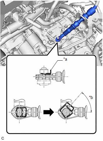
5. DISCONNECT TRANSMISSION CONTROL CABLE ASSEMBLY
| (a) While disengaging the clip as shown in the illustration, disconnect the transmission control cable assembly from the transmission control shaft lever together with the clip. |
|
6. REMOVE PARK/NEUTRAL POSITION SWITCH ASSEMBLY
| (a) Disconnect the park/neutral position switch assembly connector. |
|
.png)
| (b) Remove the nut, washer and transmission control shaft lever from the manual valve lever shaft sub-assembly. |
|
.png)
| (c) Remove the 2 bolts and park/neutral position switch assembly from the automatic transaxle case sub-assembly. NOTICE: Before removing the park/neutral position switch assembly, remove any dirt or rust on the installation portion of the manual valve lever shaft sub-assembly. Be sure to remove the park/neutral position switch assembly straight along the manual valve lever shaft sub-assembly while being careful not to deform the plate spring that supports the manual valve lever shaft sub-assembly. If the plate spring is deformed, the park/neutral position switch assembly cannot be reinstalled correctly. |
|
.png)
READ NEXT:
 Shift Lever Knob
ComponentsCOMPONENTS ILLUSTRATION *1 SHIFT LEVER KNOB SUB-ASSEMBLY - - InstallationINSTALLATION PROCEDURE 1. INSTALL SHIFT LEVER KNOB SUB-ASSEMBLY (a) Install the shift lever knob su
Components
COMPONENTS ILLUSTRATION *1 SHIFT LEVER KNOB SUB-ASSEMBLY *2 SHIFT LOCK RELEASE BUTTON COVER *3 TRANSMISSION CONTROL CABLE ASSEMBLY *4 TRANSMISSION FLOOR SHIFT ASSEMBLY *5 REA
SEE MORE:
Back Camera Internal Circuit (C2A63)
DESCRIPTION This DTC is stored when the clearance warning ECU assembly detects a signal indicating a malfunction in the rear television camera assembly via CAN communication. DTC No. Detection Item DTC Detection Condition Trouble Area C2A63 Back Camera Internal Circuit A signal indi
Cooling Fan Circuit
DESCRIPTION The ECM calculates an appropriate cooling fan speed based on the engine coolant temperature, air conditioning switch status, refrigerant pressure, engine speed and vehicle speed, and sends a signal to the cooling fan ECU (fan with motor assembly). The cooling fan ECU (fan with motor asse
