Lexus ES: Installation
INSTALLATION
CAUTION / NOTICE / HINT
HINT:
- Use the same procedure for the RH and LH sides.
- The procedure listed below is for the LH side.
PROCEDURE
1. INSTALL REAR DRIVE SHAFT INBOARD JOINT SHAFT SNAP RING LH
(a) Install a new rear drive shaft inboard joint shaft snap ring LH.
2. INSTALL REAR DRIVE SHAFT ASSEMBLY LH
(a) Coat the splines of the rear drive shaft inboard joint assembly LH with Toyota genuine differential gear oil LT 75W-85 API GL-5.
(b) Coat the rear drive shaft inboard joint shaft snap ring LH of the rear drive shaft inboard joint assembly LH with MP grease.
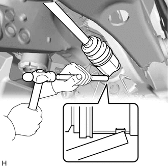
| (c) Align the inboard joint splines, and using a brass bar and a hammer, install the rear drive shaft assembly LH. NOTICE:
HINT: Confirm whether the drive shaft is securely driven in by checking the reaction force and sound. |
|
3. INSTALL REAR AXLE CARRIER SUB-ASSEMBLY
Click here .gif)
4. INSTALL REAR WHEEL
Click here
5. INSPECT FOR DIFFERENTIAL OIL LEAK
READ NEXT:
 Reassembly
REASSEMBLY CAUTION / NOTICE / HINT NOTICE:
When using a vise, place aluminum plates between the part and vise.
When using a vise, do not overtighten it.
HINT:
Use the same procedure for the
Removal
REMOVAL CAUTION / NOTICE / HINT The necessary procedures (adjustment, calibration, initialization, or registration) that must be performed after parts are removed and installed, or replaced during rea
SEE MORE:
Lost Communication with Steering Heater ECU (B14B7)
DESCRIPTION The heated steering wheel controller (steering vibration ECU) communicates with the air conditioning amplifier assembly via LIN communication. B14B7 is output when a communication malfunction is detected with the air conditioner amplifier assembly and heated steering wheel controller (st
Terminals Of Ecm
TERMINALS OF ECM HINT: The standard voltage, resistance and waveform between each pair of the ECM terminals is shown in the table below. The appropriate conditions for checking each pair of the terminals is also indicated. The result of checks should be compared with the standard voltage, resistanc
