Lexus ES: Removal
REMOVAL
CAUTION / NOTICE / HINT
The necessary procedures (adjustment, calibration, initialization, or registration) that must be performed after parts are removed and installed, or replaced during rear drive shaft assembly removal/installation are shown below.
Necessary Procedures After Parts Removed/Installed/Replaced| Replaced Part or Performed Procedure | Necessary Procedure | Effect/Inoperative Function when Necessary Procedure not Performed | Link |
|---|---|---|---|
| *1: for LED Type Turn Signal Light | |||
| Suspension, tires, etc. (The vehicle height changes because of suspension or tire replacement.) |
|
| |
| Rear television camera assembly optical axis adjustment (Back camera position setting) | Parking Assist Monitor System | | |
| Panoramic View Monitor System | | |
| Perform headlight ECU sub-assembly LH initialization*1 | Lighting System | | |
| Rear height control sensor sub-assembly LH | Perform headlight ECU sub-assembly LH initialization*1 | Lighting System | |
| Rear wheel alignment adjustment |
|
| |
CAUTION / NOTICE / HINT
HINT:
- Use the same procedure for the RH side and LH side.
- The following procedure is for the LH side.
PROCEDURE
1. REMOVE REAR WHEEL
Click here .gif)
2. REMOVE REAR AXLE CARRIER SUB-ASSEMBLY
Click here
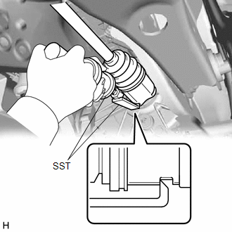
3. REMOVE REAR DRIVE SHAFT ASSEMBLY LH
| (a) Using SST, remove the rear drive shaft assembly LH from the rear differential carrier assembly. SST: 09520-01011 SST: 09520-20010 09521-02010 09521-02040 09521-02060 NOTICE:
|
|
4. REMOVE REAR DRIVE SHAFT INBOARD JOINT SHAFT SNAP RING LH
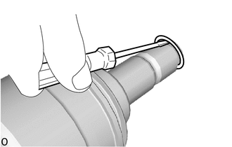
(a) Using a screwdriver, remove the rear drive shaft inboard joint shaft snap ring LH.
READ NEXT:
 4wd Control Ecu
ComponentsCOMPONENTS ILLUSTRATION *1 NO. 3 INSTRUMENT PANEL TO COWL BRACE SUB-ASSEMBLY *2 4WD ECU ASSEMBLY N*m (kgf*cm, ft.*lbf): Specified torque - - InstallationINSTALLATIO
SEE MORE:
Pressure Control Solenoid "B" Actuator Stuck Off (P07757F)
DESCRIPTION Based on signals from the transmission revolution sensors (NT and NC), the actual gear is detected. The ECM compares the actual gear with the shift schedule in the ECM memory to detect mechanical malfunctions of the solenoid valves, transmission valve body assembly and automatic transaxl
System Description
SYSTEM DESCRIPTION SLIDING ROOF SYSTEM DESCRIPTION (a) The sliding roof system controls the sliding roof operation using the sliding roof ECU (sliding roof drive gear sub-assembly). Operating the sliding roof switch (map light sub-assembly) results in electrical power being transmitted to the slidin
