Lexus ES: Hybrid/EV Powertrain Control Module Unexpected Operation (P0A1D94)
DESCRIPTION
The battery ECU assembly monitors the hybrid vehicle control ECU via CAN communication. If the battery ECU assembly detects that the hybrid vehicle control ECU is malfunctioning, it will illuminate the MIL and store a DTC.
| DTC No. | Detection Item | DTC Detection Condition | Trouble Area | MIL | Warning Indicate |
|---|---|---|---|---|---|
| P0A1D94 | Hybrid/EV Powertrain Control Module Unexpected Operation | Hybrid vehicle control ECU internal malfunction: An abnormal signal from the hybrid vehicle control ECU is detected by the battery ECU assembly. (1 trip detection logic) | Hybrid vehicle control ECU | Comes on | Master Warning Light: Comes on |
MONITOR DESCRIPTION
The battery ECU assembly monitors the hybrid vehicle control ECU via CAN communication. If the battery ECU assembly detects a malfunction in the hybrid vehicle control ECU, it will illuminate the MIL and store a DTC.
MONITOR STRATEGY
| Related DTCs | P0A1D (INF P0A1D94): Hybrid powertrain control module |
| Required sensors/components | Hybrid vehicle control ECU |
| Frequency of operation | Continuous |
| Duration | TMC's intellectual property |
| MIL operation | Immediately |
| Sequence of operation | None |
TYPICAL ENABLING CONDITIONS
| The monitor will run whenever the following DTCs are not stored | TMC's intellectual property |
| Other conditions belong to TMC's intellectual property | - |
TYPICAL MALFUNCTION THRESHOLDS
| TMC's intellectual property | - |
COMPONENT OPERATING RANGE
| Hybrid vehicle control ECU | DTC P0A1D (INF P0A1D94) is not detected |
CONFIRMATION DRIVING PATTERN
HINT:
-
After repair has been completed, clear the DTC and then check that the vehicle has returned to normal by performing the following All Readiness check procedure.
Click here
.gif)
-
When clearing the permanent DTCs, refer to the "CLEAR PERMANENT DTC" procedure.
Click here
- Connect the Techstream to the DLC3.
- Turn the power switch on (IG) and turn the Techstream on.
- Clear the DTCs (even if no DTCs are stored, perform the clear DTC procedure).
- Turn the power switch off and wait for 2 minutes or more.
- Turn the power switch on (IG) and turn the Techstream on.
-
With power switch on (IG) and wait for 2 minutes or more.[*1]
HINT:
[*1]: Normal judgment procedure.
The normal judgment procedure is used to complete DTC judgment and also used when clearing permanent DTCs.
- Enter the following menus: Powertrain / HV Battery / Utility / All Readiness.
-
Check the DTC judgment result.
HINT:
- If the judgment result shows NORMAL, the system is normal.
- If the judgment result shows ABNORMAL, the system has a malfunction.
- If the judgment result shows INCOMPLETE or N/A, perform the normal judgment procedure again.
CAUTION / NOTICE / HINT
CAUTION:
-
Before the following operations are conducted, take precautions to prevent electric shock by turning the power switch off, wearing insulated gloves, and removing the service plug grip from HV battery.
.png)
- Inspecting the high-voltage system
- Disconnecting the low voltage connector of the inverter with converter assembly
- Disconnecting the low voltage connector of the HV battery
-
To prevent electric shock, make sure to remove the service plug grip to cut off the high voltage circuit before servicing the vehicle.

-
After removing the service plug grip from the HV battery, put it in your pocket to prevent other technicians from accidentally reconnecting it while you are working on the high-voltage system.

-
After removing the service plug grip, wait for at least 10 minutes before touching any of the high-voltage connectors or terminals. After waiting for 10 minutes, check the voltage at the terminals in the inspection point in the inverter with converter assembly. The voltage should be 0 V before beginning work.

*a
Without waiting for 10 minutes
Click here
HINT:
Waiting for at least 10 minutes is required to discharge the high-voltage capacitor inside the inverter with converter assembly.
NOTICE:
After turning the power switch off, waiting time may be required before disconnecting the cable from the negative (-) auxiliary battery terminal. Therefore, make sure to read the disconnecting the cable from the negative (-) auxiliary battery terminal notices before proceeding with work.
Click here
PROCEDURE
| 1. | CHECK CONNECTOR CONNECTION CONDITION (HYBRID VEHICLE CONTROL ECU CONNECTOR) |
| (a) Check the connections of the hybrid vehicle control ECU connector. Click here OK: The connectors are connected securely and there are no contact pressure problems. |
|
| NG | .gif) | CONNECT SECURELY |
|
.gif)
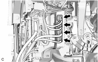
| 2. | CHECK CONNECTOR CONNECTION CONDITION (BATTERY ECU ASSEMBLY CONNECTOR) |
CAUTION:
Be sure to wear insulated gloves and protective goggles.
(a) Check that the service plug grip is not installed.
NOTICE:
After removing the service plug grip, do not turn the power switch on (READY), unless instructed by the repair manual because this may cause a malfunction.
(b) Remove the No. 1 HV battery hose.
Click here
| (c) Check the connector connections and contact pressure of the relevant terminals for the battery ECU assembly. Click here OK: The connector is connected securely and there are no contact problems. |
|
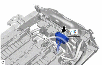
(d) Install the No. 1 HV battery hose.
| NG | | CONNECT SECURELY |
|
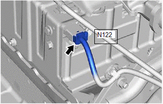
| 3. | CHECK CONNECTOR CONNECTION CONDITION (NO. 1 HYBRID BATTERY PACK WIRE)) |
CAUTION:
Be sure to wear insulated gloves and protective goggles.
(a) Check that the service plug grip is not installed.
NOTICE:
After removing the service plug grip, do not turn the power switch on (READY), unless instructed by the repair manual because this may cause a malfunction.
(b) Remove the No. 4 HV battery protector.
Click here
| (c) Check the connector connections and contact pressure of the relevant terminals for the HV battery. Click here OK: The connector is connected securely and there are no contact problems. |
|
(d) Install the No. 4 HV battery protector.
| NG | | CONNECT SECURELY |
|
| 4. | REPLACE HYBRID VEHICLE CONTROL ECU |
Click here
| NEXT | | END |
READ NEXT:
 Hybrid/EV Battery Cooling Fan 1 Circuit Short to Ground (P0A8111)
DESCRIPTION The battery cooling blower assembly speed is controlled by the battery ECU assembly. Power is supplied to the battery cooling blower assembly when the MREL terminal of the hybrid vehicle c
Hybrid/EV Battery Cooling Fan 1 Circuit Short to Auxiliary Battery or Open (P0A8115)
DESCRIPTION Refer to the description for DTC P0A8111. Click here DTC No. Detection Item DTC Detection Condition Trouble Area MIL Warning Indicate P0A8115 Hybrid/EV Battery Cooling
Hybrid/EV Battery Cooling Fan 1 Component Internal Failure (P0A8196)
DESCRIPTION Refer to the description for DTC P0A8111. Click here DTC No. Detection Item DTC Detection Condition Trouble Area MIL Warning Indicate P0A8196 Hybrid/EV Battery Cooling
SEE MORE:
The Display of the Multi-display does not Switched
DESCRIPTION The multi-display receives a signal from the clearance warning ECU assembly to change the display screen. WIRING DIAGRAM PROCEDURE 1. CHECK HARNESS AND CONNECTOR (CLEARANCE WARNING ECU ASSEMBLY - MULTI-DISPLAY ASSEMBLY) (a) Disconnect the N41 clearance warning ECU assembly conn
Pointer Displayed/not Displayed Repeatedly
WIRING DIAGRAM CAUTION / NOTICE / HINT NOTICE:
Depending on the parts that are replaced during vehicle inspection or maintenance, performing initialization, registration or calibration may be needed. Refer to Precaution for Audio and Visual System.
Click here
When replacing the radio receiv
