Lexus ES: Pointer Displayed/not Displayed Repeatedly
WIRING DIAGRAM
CAUTION / NOTICE / HINT
NOTICE:
-
Depending on the parts that are replaced during vehicle inspection or maintenance, performing initialization, registration or calibration may be needed. Refer to Precaution for Audio and Visual System.
Click here
.gif)
-
When replacing the radio receiver assembly, always replace it with a new one.
If a radio receiver assembly which was installed to another vehicle is used, the following may occur:
- A communication malfunction DTC may be stored.
- The radio receiver assembly may not operate normally.
- Inspect the fuses for circuits related to this system before performing the following procedure.
PROCEDURE
| 1. | CHECK SYMPTOMS |
(a) Recheck the situation when the malfunction occurs.
HINT:
- When a hand is rested on the remote touch screen while driving, the remote touch (remote operation controller assembly) may react to finger movements and repeatedly display and hide the pointer.
- When accelerating excessively on rough roads, the remote touch (remote operation controller assembly) may react to the acceleration and repeatedly display and hide the pointer.
| Result | Proceed to |
|---|---|
| Symptom occurs in any situation. | A |
| Symptom occurs when hand is rested on the remote touch screen while driving. | B |
| Symptom occurs when accelerating excessively on rough roads. | C |
| B | .gif) | END |
| C | | GO TO STEP 4 |
|
.gif)
| 2. | CHECK FOR FOREIGN MATTER |
(a) Check if there is any foreign matter around the remote touch screen that interferes with operation of the screen.
OK:
There is no foreign matter around the remote touch screen that interferes with operation of the screen.
| NG | | REMOVE FOREIGN MATTER (CHECK OPERATION AGAIN) |
|
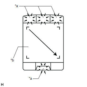
| 3. | REMOTE TOUCH (REMOTE OPERATION CONTROLLER ASSEMBLY) SELF CHECK (CHECK REMOTE TOUCH SCREEN OPERATION POSITION RECOGNITION CONDITION) |
(a) Enter self-diagnostic mode.
Click here
| (b) Operate the remote touch screen diagonally from the upper left to the lower right and check that the brightness of the switch illumination changes. NOTICE: Since the remote touch screen may recognize a pinch in/out or flick operation if operated with 2 fingers, always use 1 finger to operate the remote touch screen in self-diagnostic mode. OK: Brightness changes according to remote touch screen operation.
HINT: When the switch illumination blinks, the remote touch (remote operation controller assembly) has stored a DTC. |
|
| A | | REPLACE RADIO RECEIVER ASSEMBLY |
| B | | REPLACE REMOTE TOUCH (REMOTE OPERATION CONTROLLER ASSEMBLY) |
| 4. | CHECK CONNECTOR CONNECTION CONDITION |
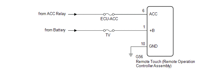
(a) Check if the G56 remote touch (remote operation controller assembly) connector is securely connected.
OK:
The connector is securely connected.
| NG | | SECURELY CONNECTED |
|
| 5. | CHECK HARNESS AND CONNECTOR (REMOTE TOUCH (REMOTE OPERATION CONTROLLER ASSEMBLY) POWER SOURCE) |
(a) Disconnect the G56 remote touch (remote operation controller assembly) connector.
(b) Measure the resistance according to the value(s) in the table below.
Standard Resistance:
| Tester Connection | Condition | Specified Condition |
|---|---|---|
| G56-10 (GND) - Body ground | Always | Below 1 Ω |
(c) Measure the voltage according to the value(s) in the table below.
Standard Voltage:
| Tester Connection | Condition | Specified Condition |
|---|---|---|
| G56-1 (+B) - Body ground | Always | 11 to 14 V |
| G56-6 (ACC) - Body ground | Engine switch on (ACC) | 11 to 14 V |
| OK | | REPLACE REMOTE TOUCH (REMOTE OPERATION CONTROLLER ASSEMBLY) |
| NG | | REPAIR OR REPLACE HARNESS OR CONNECTOR |
READ NEXT:
 Pointer not Displayed on Screen or Pointer does not Move
CAUTION / NOTICE / HINT NOTICE:
Depending on the parts that are replaced during vehicle inspection or maintenance, performing initialization, registration or calibration may be needed. Refer to Pre
Poor Sound Quality in All Modes (Low Volume)
PROCEDURE 1. CHECK AUDIO SETTINGS (a) Set treble, middle and bass to the initial values and check that the sound is normal. OK: The sound returns to normal. HINT: Sound quality adjustment me
Portable Player cannot be Connected Manually/Automatically
CAUTION / NOTICE / HINT HINT: Some versions of "Bluetooth" compatible audio players may not function properly, or the functions may be limited using the radio receiver assembly, even if the portable a
SEE MORE:
Front Acceleration Sensor RH Malfunction (C1715-C1717,C1796-C1798)
DESCRIPTION The acceleration sensor (up and down G sensor) detects the upward and downward acceleration of the vehicle and outputs it as a voltage to the absorber control ECU. The 3 up and down G sensors are installed in the driver side instrument panel, the passenger side instrument panel and the a
Pointer Displayed/not Displayed Repeatedly
WIRING DIAGRAM CAUTION / NOTICE / HINT NOTICE:
Depending on the parts that are replaced during vehicle inspection or maintenance, performing initialization, registration or calibration may be needed. Refer to Precaution for Audio and Visual System.
Click here
When replacing the radio receiv
