
Lexus ES: Hood
Opening the hood
1. Pull the hood lock release lever.
The hood will pop up slightly.
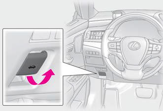
2. Pull up the auxiliary catch lever and lift the hood.

WARNING
■Pre-driving check Check that the hood is fully closed and locked.
If the hood is not locked properly, it may open while the vehicle is in motion and cause an accident, which may result in death or serious injury.
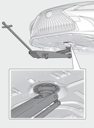
Positioning a floor jack
When using a floor jack, follow the instructions in the manual provided with the jack and perform the operation safely.
When raising your vehicle with a floor jack, position the jack correctly.
Improper placement may damage your vehicle or cause injury.
Location of the jack point
■ Front
■ Rear

READ NEXT:
 Engine compartment
Components
Fuse boxes
Engine oil filler cap
Engine oil level dipstick
Brake fluid reservoir
Radiator
Electric cooling fan
Condenser
Power control unit coolant reservoir
Engine
12-volt battery
Location
The 12-volt battery is located on the
right-hand side of the trunk.
■Before recharging
When recharging, the 12-volt battery produces
hydrogen gas which is flammable
and explosive. T
Tires
Replace or rotate tires in accordance
with maintenance schedules
and treadwear.
Checking tires
Check if the treadwear indicators are
showing on the tires. Also check the
tires for uneven wear, s
SEE MORE:
Problem Symptoms Table
PROBLEM SYMPTOMS TABLE NOTICE:
Before performing troubleshooting, change the grille shutter control mode to maintenance mode.
Click here
If the swing grille actuator assembly has been replaced with a new one, perform initialization and change the grille shutter control mode.
Click here
Drive Motor "A" Temperature Sensor Voltage Out of Range (P0A2A1C,P0A2A1F)
DTC SUMMARY MALFUNCTION DESCRIPTION These DTCs are stored when the motor temperature sensor output is abnormal. The cause of this malfunction may be one of the following: Motor temperature sensor malfunction
Internal motor temperature sensor malfunction
Open or short in motor temperature sensor
© 2016-2026 Copyright www.lexguide.net
