Lexus ES: Headlight Swivel ECU LH Communication (B2410,B2411)
DESCRIPTION
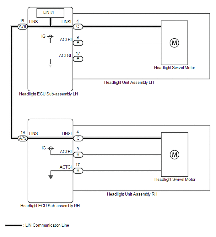
Each headlight ECU sub-assembly and headlight swivel motor communicate via LIN communication.
The headlight swivel motor operates according to power supplied and automatic headlight beam level control signals from its respective headlight ECU sub-assembly and sends its operating state to the headlight ECU sub-assembly.
| DTC No. | Detection Item | DTC Detection Condition | Trouble Area | DTC Output from |
|---|---|---|---|---|
| B2410 | Headlight Swivel ECU LH Communication |
|
| AFS |
| B2411 | Headlight Swivel ECU RH Communication |
|
| AFS |
WIRING DIAGRAM
CAUTION / NOTICE / HINT
NOTICE:
-
If the headlight ECU sub-assembly LH has been replaced, it is necessary to synchronize the vehicle information and initialize the headlight ECU sub-assembly LH.
Click here
.gif)
- When replacing the headlight ECU sub-assembly LH, always replace it with a new one. If a headlight ECU sub-assembly LH which was installed to another vehicle is used, the information stored in it will not match the information from the vehicle and a DTC may be stored.
PROCEDURE
| 1. | CLEAR DTC |
(a) Connect the Techstream to the DLC3.
(b) Turn the engine switch on (IG).
(c) Turn the Techstream on.
(d) Enter the following menus: Body Electrical / AFS / Trouble Codes.
(e) Clear the DTCs.
Body Electrical > AFS > Clear DTCs
|
.gif)
| 2. | CHECK FOR DTC |
(a) Connect the Techstream to the DLC3.
(b) Turn the engine switch on (IG).
(c) Wait 10 seconds or more.
(d) Turn the Techstream on.
(e) Enter the following menus: Body Electrical / AFS / Trouble Codes.
(f) Check for DTCs.
Body Electrical > AFS > Trouble CodesOK:
DTC B2410 and B2411 are not output.
| Result | Proceed to |
|---|---|
| OK | A |
| NG (DTC B2410 is output) | B |
| NG (DTC B2411 is output) | C |
| NG (DTC B2410 and B2411 are output) | D |
| A | .gif) | USE SIMULATION METHOD TO CHECK |
| C | | GO TO STEP 4 |
| D | | GO TO STEP 7 |
|
| 3. | INSPECT HEADLIGHT ECU SUB-ASSEMBLY LH |
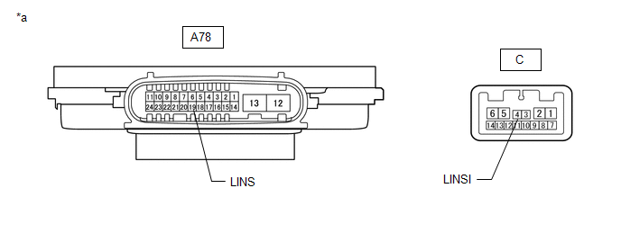
| *a | Component without harness connected (Headlight ECU Sub-assembly LH) | - | - |
(a) Remove the headlight ECU sub-assembly LH.
Click here
(b) Measure the resistance according to the value(s) in the table below.
Standard Resistance:
| Tester Connection | Condition | Specified Condition |
|---|---|---|
| A78-19 (LINS) - C-4 (LINSI) | Always | Below 1 Ω |
| OK | | REPLACE HEADLIGHT UNIT ASSEMBLY LH |
| NG | | REPLACE HEADLIGHT ECU SUB-ASSEMBLY LH |
| 4. | CHECK HARNESS AND CONNECTOR (HEADLIGHT ECU SUB-ASSEMBLY LH - HEADLIGHT ECU SUB-ASSEMBLY RH) |
(a) Disconnect the A78 headlight ECU sub-assembly LH connector.
(b) Disconnect the A79 headlight ECU sub-assembly RH connector.
(c) Measure the resistance according to the value(s) in the table below.
Standard Resistance:
| Tester Connection | Condition | Specified Condition |
|---|---|---|
| A78-19 (LINS) - A79-19 (LINS) | Always | Below 1 Ω |
| NG | | REPAIR OR REPLACE HARNESS OR CONNECTOR |
|
| 5. | CHECK HEADLIGHT ECU SUB-ASSEMBLY LH (LINS TERMINAL SIGNAL OUTPUT) |
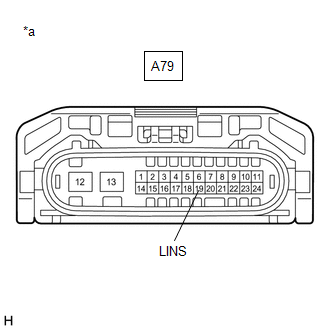
| *a | Front view of wire harness connector (to Headlight ECU Sub-assembly RH) |
(a) Connect the A78 headlight ECU sub-assembly LH connector.
(b) Using a Techstream, check the waveform.
OK:
| Tester Connection | Condition | Specified Condition |
|---|---|---|
| A79-19 (LINS) - Body ground | Engine switch on (IG) | Pulse generation |
| NG | | REPLACE HEADLIGHT ECU SUB-ASSEMBLY LH |
|
| 6. | INSPECT HEADLIGHT ECU SUB-ASSEMBLY RH |

| *a | Component without harness connected (Headlight ECU Sub-assembly RH) | - | - |
(a) Remove the headlight ECU sub-assembly RH.
Click here
(b) Measure the resistance according to the value(s) in the table below.
Standard Resistance:
| Tester Connection | Condition | Specified Condition |
|---|---|---|
| A79-19 (LINS) - C-4 (LINSI) | Always | Below 1 Ω |
| OK | | REPLACE HEADLIGHT UNIT ASSEMBLY RH |
| NG | | REPLACE HEADLIGHT ECU SUB-ASSEMBLY RH |
| 7. | CHECK HARNESS AND CONNECTOR (HEADLIGHT ECU SUB-ASSEMBLY LH - HEADLIGHT ECU SUB-ASSEMBLY RH) |
(a) Disconnect the A78 headlight ECU sub-assembly LH connector.
(b) Disconnect the A79 headlight ECU sub-assembly RH connector.
(c) Measure the resistance according to the value(s) in the table below.
Standard Resistance:
| Tester Connection | Condition | Specified Condition |
|---|---|---|
| A78-19 (LINS) or A79-19 (LINS) - Body ground | Always | 10 kΩ or higher |
| NG | | REPAIR OR REPLACE HARNESS OR CONNECTOR |
|
| 8. | CLEAR DTC |
(a) Connect the A78 headlight ECU sub-assembly LH connector.
(b) Connect the Techstream to the DLC3.
(c) Turn the engine switch on (IG).
(d) Turn the Techstream on.
(e) Enter the following menus: Body Electrical / AFS / Trouble Codes.
(f) Clear the DTCs.
Body Electrical > AFS > Clear DTCs
|
| 9. | CHECK FOR DTC |
(a) Connect the Techstream to the DLC3.
(b) Turn the engine switch on (IG).
(c) Wait 10 seconds or more.
(d) Turn the Techstream on.
(e) Enter the following menus: Body Electrical / AFS / Trouble Codes.
(f) Check for DTCs.
Body Electrical > AFS > Trouble Codes| Result | Proceed to |
|---|---|
| DTC B2411 is output | A |
| DTC B2410 and B2411 are output | B |
| B | | GO TO STEP 13 |
|
| 10. | CHECK HEADLIGHT ECU SUB-ASSEMBLY RH |
(a) Remove the headlight ECU sub-assembly RH.
Click here
(b) Connect the A79 headlight ECU sub-assembly RH connector.
|
| 11. | CLEAR DTC |
(a) Connect the Techstream to the DLC3.
(b) Turn the engine switch on (IG).
(c) Turn the Techstream on.
(d) Enter the following menus: Body Electrical / AFS / Trouble Codes.
(e) Clear the DTCs.
Body Electrical > AFS > Clear DTCs
|
| 12. | CHECK FOR DTC |
(a) Connect the Techstream to the DLC3.
(b) Turn the engine switch on (IG).
(c) Wait 10 seconds or more.
(d) Turn the Techstream on.
(e) Enter the following menus: Body Electrical / AFS / Trouble Codes.
(f) Check for DTCs.
Body Electrical > AFS > Trouble Codes| Result | Proceed to |
|---|---|
| DTC B2411 is output | A |
| DTC B2410 and B2411 are output | B |
| A | | REPLACE HEADLIGHT UNIT ASSEMBLY RH |
| B | | REPLACE HEADLIGHT ECU SUB-ASSEMBLY RH |
| 13. | CHECK HEADLIGHT ECU SUB-ASSEMBLY LH |
(a) Remove the headlight ECU sub-assembly LH.
Click here
(b) Connect the A78 headlight ECU sub-assembly LH connector.
(c) Connect the A79 headlight ECU sub-assembly RH connector.
|
| 14. | CLEAR DTC |
(a) Connect the Techstream to the DLC3.
(b) Turn the engine switch on (IG).
(c) Turn the Techstream on.
(d) Enter the following menus: Body Electrical / AFS / Trouble Codes.
(e) Clear the DTCs.
Body Electrical > AFS > Clear DTCs
|
| 15. | CHECK FOR DTC |
(a) Connect the Techstream to the DLC3.
(b) Turn the engine switch on (IG).
(c) Wait 10 seconds or more.
(d) Turn the Techstream on.
(e) Enter the following menus: Body Electrical / AFS / Trouble Codes.
(f) Check for DTCs.
Body Electrical > AFS > Trouble Codes| Result | Proceed to |
|---|---|
| DTC B2410 is output | A |
| DTC B2410 and B2411 are output | B |
| A | | REPLACE HEADLIGHT UNIT ASSEMBLY LH |
| B | | REPLACE HEADLIGHT ECU SUB-ASSEMBLY LH |
READ NEXT:
 Headlight Swivel Motor LH (B2412,B2413,B2417,B2418)
DESCRIPTION The headlight ECU sub-assembly LH sends automatic headlight beam level control signals to each headlight swivel motor and headlight leveling motor via LIN communication. Each headlight ECU
Steering Position Sensor (B2414)
DESCRIPTION The headlight ECU sub-assembly LH receives steering angle signals from the steering sensor via CAN communication and performs light control. for LED Type Turn Signal Light DTC No. Det
Vehicle Speed Sensor (B2415)
DESCRIPTION The headlight ECU sub-assembly LH receives speed signals from the skid control ECU (brake actuator assembly) via CAN communication and performs light control. for LED Type Turn Signal Ligh
SEE MORE:
Front Camera Current Malfunction (C1682)
DESCRIPTION DTC C1682 is stored if the parking assist ECU judges as a result of its self check that there is a problem with the current supplied from the front television camera assembly connected to the parking assist ECU. DTC No. Detection Item DTC Detection Condition Trouble Area C16
How To Proceed With Troubleshooting
CAUTION / NOTICE / HINT HINT: *: Use the Techstream. PROCEDURE 1. VEHICLE BROUGHT TO WORKSHOP
NEXT 2. CUSTOMER PROBLEM ANALYSIS (a) Interview the customer and confirm the problem. Click here
NEXT 3. CHECK DTC AND FREEZE FRAME DATA* (a) C
