Lexus ES: GVIF Disconnected (from Extension Module to H/U) (B153A)
DESCRIPTION
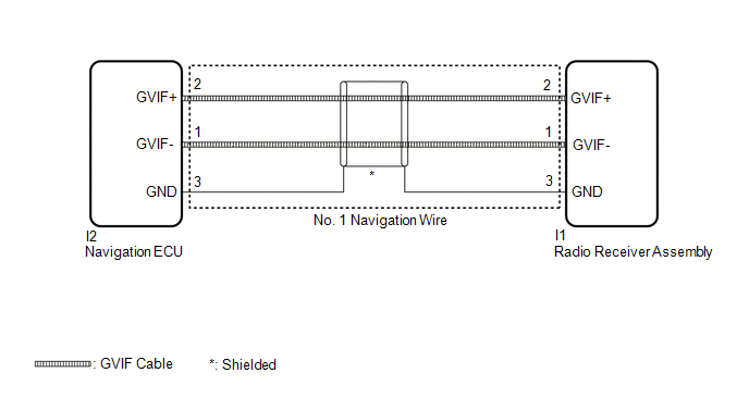
The radio receiver assembly and navigation ECU are connected via video signal (digital) lines.
This DTC is stored when a video signal (digital) line is disconnected.
| DTC No. | Detection Item | DTC Detection Condition | Trouble Area |
|---|---|---|---|
| B153A | GVIF Disconnected (from Extension Module to H/U) | GVIF disconnected (from navigation ECU to radio receiver assembly) |
|
WIRING DIAGRAM
CAUTION / NOTICE / HINT
NOTICE:
-
Depending on the parts that are replaced during vehicle inspection or maintenance, performing initialization, registration or calibration may be needed. Refer to Precaution for Navigation System.
Click here
.gif)
-
When replacing the radio receiver assembly or navigation ECU, always replace it with a new one. If a radio receiver assembly or navigation ECU which was installed to another vehicle is used, the following may occur:
- A communication malfunction DTC may be stored.
- The radio receiver assembly or navigation ECU may not operate normally.
PROCEDURE
| 1. | CHECK DTC |
(a) Clear the DTCs.
Body Electrical > Navigation System > Clear DTCs(b) Turn the engine switch off.
(c) Turn the engine switch on (IG).
(d) Press the "MAP" switch and check for DTCs.
Body Electrical > Navigation System > Trouble CodesOK:
No DTCs are output.
| OK |  | USE SIMULATION METHOD TO CHECK |
|

| 2. | CHECK NO. 1 NAVIGATION WIRE (RADIO RECEIVER ASSEMBLY - NAVIGATION ECU) |
| (a) Disconnect the I1 radio receiver assembly connector. |
|
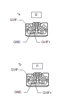
(b) Disconnect the I2 navigation ECU connector.
(c) Measure the resistance according to the value(s) in the table below.
Standard Resistance:
| Tester Connection | Condition | Specified Condition |
|---|---|---|
| I1-1 (GVIF-) - I2-1 (GVIF-) | Always | Below 1 Ω |
| I1-2 (GVIF+) - I2-2 (GVIF+) | Always | Below 1 Ω |
| I1-3 (GND) - I2-3 (GND) | Always | Below 1 Ω |
| NG | | REPLACE NO. 1 NAVIGATION WIRE |
|
| 3. | REPLACE NAVIGATION ECU |
(a) Replace the navigation ECU with a new or known good one.
Click here
|
| 4. | CHECK DTC |
(a) Clear the DTCs.
Body Electrical > Navigation System > Clear DTCs(b) Turn the engine switch off.
(c) Turn the engine switch on (IG).
(d) Press the "MAP" switch and check for DTCs.
Body Electrical > Navigation System > Trouble CodesOK:
No DTCs are output.
| OK | | END (NAVIGATION ECU IS DEFECTIVE) |
| NG | | REPLACE RADIO RECEIVER ASSEMBLY |
READ NEXT:
 Touch Pad Vibration Driver Malfunction (B155A)
DESCRIPTION This DTC is stored if the remote touch (remote operation controller assembly) detects a malfunction in itself, such as internal hardware failure or remote touch screen vibration driver mal
Touch Pad Memory Module Malfunction (B155B)
DESCRIPTION This DTC is stored if the remote touch (remote operation controller assembly) detects a malfunction in itself, such as internal hardware failure or remote touch screen memory module malfun
AV Signal Stoppage (Low Battery Voltage) (B158F)
DESCRIPTION This DTC is stored when a video or audio signal is interrupted due to battery voltage input to the radio receiver assembly dropping temporarily. DTC No. Detection Item DTC Detection
SEE MORE:
Installation
INSTALLATION PROCEDURE 1. INSTALL FUEL SUCTION TUBE WITH PUMP AND GAUGE ASSEMBLY (a) Install a new fuel suction tube set gasket to the fuel tank assembly. (b) Set the fuel suction tube with pump and gauge assembly to the fuel tank assembly. NOTICE: Be careful not to bend the arm of the fuel sender g
Remote Control System does not Operate
DESCRIPTION The main body ECU (multiplex network body ECU) receives remote control signals from the driver door key cylinder or wireless transmitter. Then, the main body ECU (multiplex network body ECU) activates the power window motor and sends the remote control signals to the sliding roof ECU (sl
