Lexus ES: AV Signal Stoppage (Low Battery Voltage) (B158F)
DESCRIPTION
This DTC is stored when a video or audio signal is interrupted due to battery voltage input to the radio receiver assembly dropping temporarily.
| DTC No. | Detection Item | DTC Detection Condition | Trouble Area |
|---|---|---|---|
| B158F | AV Signal Stoppage (Low Battery Voltage) | A video or audio signal is interrupted when the battery voltage drops |
|
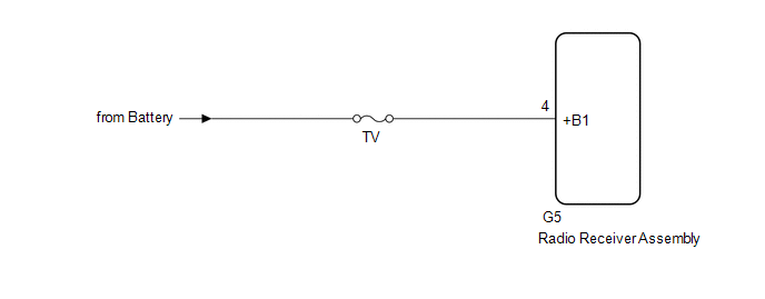
WIRING DIAGRAM
CAUTION / NOTICE / HINT
NOTICE:
- Inspect the fuses for circuits related to this system before performing the following procedure.
-
Depending on the parts that are replaced during vehicle inspection or maintenance, performing initialization, registration or calibration may be needed. Refer to Precaution for Navigation System.
Click here
.gif)
-
When replacing the radio receiver assembly, always replace it with a new one. If a radio receiver assembly which was installed to another vehicle is used, the following may occur:
- A communication malfunction DTC may be stored.
- The radio receiver assembly may not operate normally.
PROCEDURE
| 1. | CHECK VEHICLE SIGNAL (OPERATION CHECK) |
| (a) Enter the "Vehicle Signal Check Mode" screen. Refer to Check Vehicle Signal in Operation Check. Click here |
|
.png)
(b) Measure the battery voltage.
Standard Voltage:
11 to 14 V
HINT:
This display is updated once per second.
| NG |  | GO TO STEP 3 |
|

| 2. | CHECK DTC |
(a) Clear the DTCs.
Body Electrical > Navigation System > Clear DTCs(b) Recheck for DTCs and check that no DTCs are output.
Body Electrical > Navigation System > Trouble CodesOK:
No DTCs are output.
| OK | | END |
| NG | | REPLACE RADIO RECEIVER ASSEMBLY |
| 3. | CHECK HARNESS AND CONNECTOR (RADIO RECEIVER ASSEMBLY POWER SOURCE) |
(a) Disconnect the G5 radio receiver assembly connector.
(b) Measure the voltage according to the value(s) in the table below.
Standard Voltage:
| Tester Connection | Condition | Specified Condition |
|---|---|---|
| G5-4 (+B1) - Body ground | Always | 11 to 14 V |
| OK | | REPLACE RADIO RECEIVER ASSEMBLY |
| NG | | REPAIR OR REPLACE HARNESS OR CONNECTOR |
READ NEXT:
 Lost Communication with Haptic Device (B1323-B1326)
DESCRIPTION These DTCs are stored when communication between the radio receiver assembly and remote touch (remote operation controller assembly), combination meter assembly, headup display (meter mirr
NTSC Disconnected (from Park Assist/Monitoring ECU) (B1535,C1622)
DESCRIPTION These DTCs are stored if the radio receiver assembly judges that the signals or signal lines between the rear television camera assembly and the multi-display assembly are not normal as a
Extension Module Disconnected 2 (B1543)
DESCRIPTION If the radio receiver assembly cannot detect the navigation ECU for a certain period of time (90 seconds) after the engine switch is turned on (ACC) and the radio receiver assembly confirm
SEE MORE:
Data List / Active Test
DATA LIST / ACTIVE TEST DATA LIST NOTICE: In the table below, the values listed under "Normal Condition" are reference values. Do not depend solely on these reference values when deciding whether a part is faulty or not. HINT: Using the Techstream to read the Data List allows the values or states of
Removal
REMOVAL CAUTION / NOTICE / HINT The necessary procedures (adjustment, calibration, initialization, or registration) that must be performed after parts are removed and installed, or replaced during rear combination light assembly removal/installation are shown below. Necessary Procedure After Parts R
