Lexus ES: Voice Recognition Microphone Disconnected (B1579)
DESCRIPTION
The radio receiver assembly and telephone microphone assembly are connected to each other using the microphone connection detection signal lines.
This DTC is stored when a microphone connection detection signal line is disconnected.
| DTC No. | Detection Item | DTC Detection Condition | Trouble Area |
|---|---|---|---|
| B1579 | Voice Recognition Microphone Disconnected | Microphone signal is lost. |
|
- *: w/ Manual (SOS) Switch
WIRING DIAGRAM
w/o Manual (SOS) Switch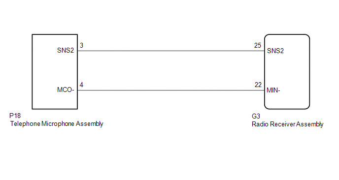 w/ Manual (SOS) Switch
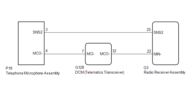
CAUTION / NOTICE / HINT
NOTICE:
-
Depending on the parts that are replaced during vehicle inspection or maintenance, performing initialization, registration or calibration may be needed. Refer to Precaution for Navigation System.
Click here
.gif)
-
When replacing the radio receiver assembly, always replace it with a new one. If a radio receiver assembly which was installed to another vehicle is used, the following may occur:
- A communication malfunction DTC may be stored.
- The radio receiver assembly may not operate normally.
-
Before replacing the DCM (telematics transceiver), refer to Registration.
Click here
PROCEDURE
| 1. | INSPECT RADIO RECEIVER ASSEMBLY |
| (a) Measure the resistance according to the value(s) in the table below. Standard Resistance:
|
|
| NG |  | REPLACE RADIO RECEIVER ASSEMBLY |
|

| 2. | CHECK MODEL |
(a) Choose the model to be inspected.
| Result | Proceed to |
|---|---|
| w/ Manual (SOS) Switch | A |
| w/o Manual (SOS) Switch | B |
| B | | GO TO STEP 7 |
|
| 3. | CHECK HARNESS AND CONNECTOR (DCM (TELEMATICS TRANSCEIVER) - TELEPHONE MICROPHONE ASSEMBLY) |
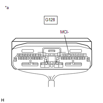
(a) Disconnect the G128 DCM (telematics transceiver) connector.
(b) Disconnect the P18 telephone microphone assembly connector.
(c) Measure the resistance according to the value(s) in the table below.
Standard Resistance:
| Tester Connection | Condition | Specified Condition |
|---|---|---|
| G128-7 (MCI-) - P18-4 (MCO-) | Always | Below 1 Ω |
| G128-7 (MCI-) or P18-4 (MCO-) - Body ground | Always | 10 kΩ or higher |
| NG | | REPAIR OR REPLACE HARNESS OR CONNECTOR |
|
| 4. | CHECK HARNESS AND CONNECTOR (RADIO RECEIVER ASSEMBLY - DCM (TELEMATICS TRANSCEIVER)) |
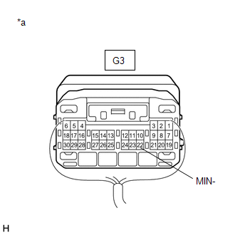
(a) Disconnect the G3 radio receiver assembly connector.
(b) Disconnect the G128 DCM (telematics transceiver) connector.
(c) Measure the resistance according to the value(s) in the table below.
Standard Resistance:
| Tester Connection | Condition | Specified Condition |
|---|---|---|
| G3-22 (MIN-) - G128-32 (MCO-) | Always | Below 1 Ω |
| G3-22 (MIN-) or G128-32 (MCO-) - Body ground | Always | 10 kΩ or higher |
| NG | | REPAIR OR REPLACE HARNESS OR CONNECTOR |
|
| 5. | CHECK HARNESS AND CONNECTOR (RADIO RECEIVER ASSEMBLY - TELEPHONE MICROPHONE ASSEMBLY) |
(a) Disconnect the G3 radio receiver assembly connector.
(b) Disconnect the P18 telephone microphone assembly connector.
(c) Measure the resistance according to the value(s) in the table below.
Standard Resistance:
| Tester Connection | Condition | Specified Condition |
|---|---|---|
| G3-25 (SNS2) - P18-3 (SNS2) | Always | Below 1 Ω |
| G3-25 (SNS2) or P18-3 (SNS2) - Body ground | Always | 10 kΩ or higher |
| NG | | REPAIR OR REPLACE HARNESS OR CONNECTOR |
|
| 6. | INSPECT DCM (TELEMATICS TRANSCEIVER) |
(a) Reconnect the G128 DCM (telematics transceiver) connector.
(b) Reconnect the G3 radio receiver assembly connector.
| (c) Measure the resistance according to the value(s) in the table below. Standard Resistance:
|
|
(d) Proceed to the next step based on the inspection result.
| OK | | GO TO STEP 8 |
| NG | | REPLACE DCM (TELEMATICS TRANSCEIVER) |
| 7. | CHECK HARNESS AND CONNECTOR (RADIO RECEIVER ASSEMBLY - TELEPHONE MICROPHONE ASSEMBLY) |
(a) Disconnect the G3 radio receiver assembly connector.
(b) Disconnect the P18 telephone microphone assembly connector.
(c) Measure the resistance according to the value(s) in the table below.
Standard Resistance:
| Tester Connection | Condition | Specified Condition |
|---|---|---|
| G3-25 (SNS2) - P18-3 (SNS2) | Always | Below 1 Ω |
| G3-22 (MIN-) - P18-4 (MCO-) | Always | Below 1 Ω |
| G3-25 (SNS2) or P18-3 (SNS2) - Body ground | Always | 10 kΩ or higher |
| G3-22 (MIN-) or P18-4 (MCO-) - Body ground | Always | 10 kΩ or higher |
| NG | | REPAIR OR REPLACE HARNESS OR CONNECTOR |
|
| 8. | INSPECT TELEPHONE MICROPHONE ASSEMBLY |
(a) Remove the telephone microphone assembly.
Click here
| (b) Measure the resistance according to the value(s) in the table below. Standard Resistance:
|
|
.png)
| OK | | REPLACE RADIO RECEIVER ASSEMBLY |
| NG | | REPLACE TELEPHONE MICROPHONE ASSEMBLY |
READ NEXT:
 USB Device Malfunction (B1585)
DESCRIPTION This DTC is stored when a malfunction occurs in a connected device. DTC No. Detection Item DTC Detection Condition Trouble Area B1585 USB Device Malfunction When any of th
Black Screen
PROCEDURE 1. CHECK DISPLAY SETTING (a) Check that the display is not in screen off mode. OK: The display setting is not in screen off mode. NG CHANGE SCREEN TO SCREEN ON MODE
Camera ECU Malfunction (C1610)
DESCRIPTION This DTC is stored when a malfunction occurs in the parking assist monitor system*1 or panoramic view monitor system*2. DTC No. Detection Item DTC Detection Condition Trouble Area
SEE MORE:
Problem Symptoms Table
PROBLEM SYMPTOMS TABLE HINT: Use the table below to help determine the cause of problem symptoms. If multiple suspected areas are listed, the potential causes of the symptoms are listed in order of probability in the "Suspected Area" column of the table. Check each symptom by checking the suspected
Data List / Active Test
DATA LIST / ACTIVE TEST ACTIVE TEST HINT: Using the Techstream to perform Active Tests allows relays, VSVs, actuators and other items to be operated without removing any parts. This non-intrusive functional inspection can be very useful because intermittent operation may be discovered before parts o
