Lexus ES: Front Wiper Rubber
Components
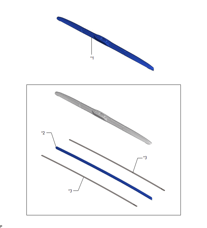
COMPONENTS
ILLUSTRATION
|
*1 |
FRONT WIPER BLADE |
*2 |
WIPER RUBBER |
|
*3 |
FRONT WIPER RUBBER BACKING PLATE |
- |
- |
Removal
REMOVAL
CAUTION / NOTICE / HINT
NOTICE:
Make sure to hold the front wiper arm while lifting it, as lifting the front wiper arm by the front wiper blade may damage or deform the front wiper blade.
HINT:
- Use the same procedure for the RH side and LH side.
- The following procedure is for the LH side.
PROCEDURE
1. REMOVE FRONT WIPER BLADE
(a) Turn the engine switch (for Gasoline Model) or power switch (for HV Model) on (IG).
(b) Turn the engine switch (for Gasoline Model) or power switch (for HV Model) off and move the windshield wiper switch assembly to the MIST position and hold it for 2 seconds or more.
HINT:
If the front wiper arm and blade assemblies do not move to the service position, turn the engine switch (for Gasoline Model) or power switch (for HV Model) on (IG) and then perform this step again.
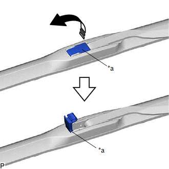
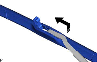
(c) Pull up the holder of the front wiper blade as shown in the illustration.
|
*a |
Holder |
.png) |
Remove in this Direction |
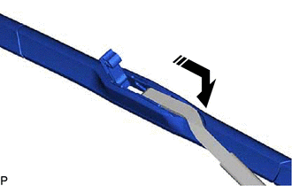
(d) Remove the front wiper blade from the front wiper arm as shown in the illustration.
NOTICE:
Place a piece of cloth between the front wiper arm and windshield glass to avoid damaging the windshield glass.
|
|
Remove in this Direction |
2. REMOVE WIPER RUBBER
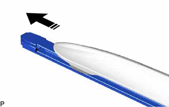
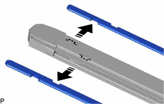
(a) Remove the wiper rubber with the front wiper rubber backing plates from the front wiper blade as shown in the illustration.
|
|
Remove in this Direction |
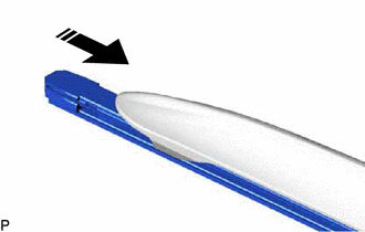
(b) Remove the 2 front wiper rubber backing plates from the wiper rubber as shown in the illustration.
|
|
Remove in this Direction |
Installation
INSTALLATION
CAUTION / NOTICE / HINT
NOTICE:
Make sure to hold the front wiper arm while lifting it, as lifting the front wiper arm by the front wiper blade may damage or deform the front wiper blade.
HINT:
- Use the same procedure for the RH side and LH side.
- The following procedure is for the LH side.
PROCEDURE
1. INSTALL WIPER RUBBER
(a) Install the 2 front wiper rubber backing plates to the wiper rubber as shown in the illustration.
.png) |
Install in this Direction |
NOTICE:
- Align the protrusions on the wiper rubber and the notches of the backing plates.
- Align the curves of the backing plates and the windshield glass.
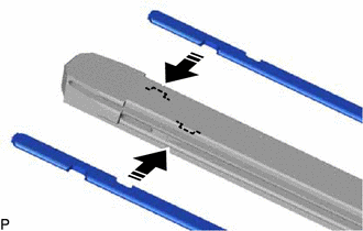
(b) Install the wiper rubber with the front wiper rubber backing plates to the front wiper blade as shown in the illustration.
|
|
Install in this Direction |
NOTICE:
Push the wiper rubber and front wiper backing plates into the front wiper blade strongly to engage them securely.
2. INSTALL FRONT WIPER BLADE
(a) Install the front wiper blade to the front wiper arm as shown in the illustration.
|
|
Install in this Direction |
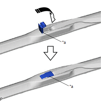
(b) Rotate the holder of the front wiper blade as shown in the illustration.
|
*a |
Holder |
|
|
Install in this Direction |
(c) Turn the engine switch (for Gasoline Model) or power switch (for HV Model) on (IG).
(d) Operate the windshield wiper switch assembly to return the front wiper arm and blade assemblies to their original position.
(e) Turn the engine switch (for Gasoline Model) or power switch (for HV Model) off.
READ NEXT:
 Outside Vehicle
OUTSIDE VEHICLE
These are maintenance and inspection items that are considered to be
the owner's responsibility.
The owner can do them or they can have them done at a service center
Inside Vehicle
INSIDE VEHICLE
These are maintenance and inspection items that are considered to be
the owner's responsibility.
The owner can do them or they can have them done at a service center.
SEE MORE:
Inspection
INSPECTION PROCEDURE 1. INSPECT REAR LIGHT ASSEMBLY LH *a Component without harness connected (Rear Light Assembly LH) (a) Apply auxiliary battery voltage to the rear light assembly LH and check that the lights illuminate. OK: Measurement Condition Specified Condition Auxiliary ba
Hybrid/EV Battery Precharge Contactor Circuit Short to Ground (P0AE411)
DESCRIPTION The SMRs (System Main Relays) are the relays that connect or disconnect the high-voltage system in accordance with commands from the hybrid vehicle control ECU. There are 3 SMRs and 1 system main resistor. SMRB, SMRP, SMRG and the system main resistor are located in the HV battery juncti
