Lexus ES: Front Passenger Side Power Window Switch
Components
COMPONENTS
ILLUSTRATION
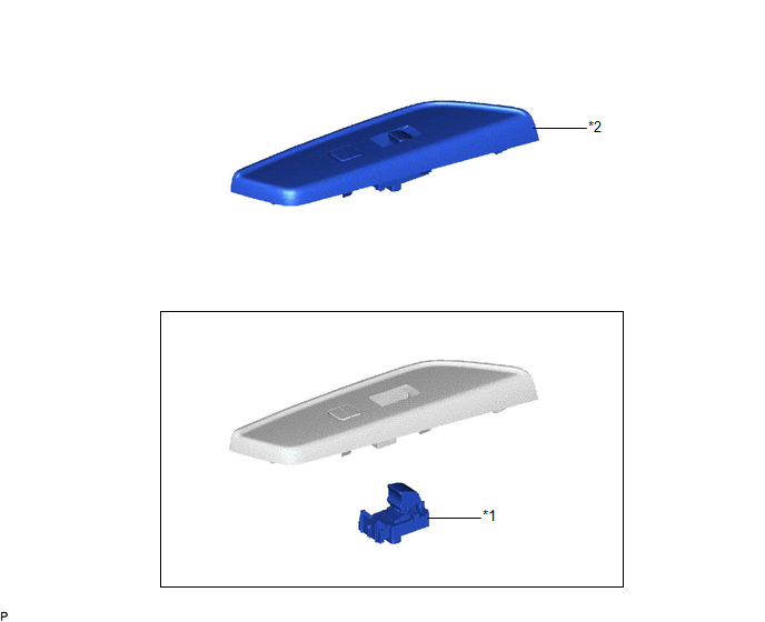
| *1 | POWER WINDOW REGULATOR SWITCH ASSEMBLY | *2 | POWER WINDOW REGULATOR SWITCH ASSEMBLY WITH FRONT DOOR UPPER ARMREST BASE PANEL |
Removal
REMOVAL
PROCEDURE
1. REMOVE POWER WINDOW REGULATOR SWITCH ASSEMBLY WITH FRONT DOOR UPPER ARMREST BASE PANEL
Click here .gif)
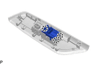
2. REMOVE POWER WINDOW REGULATOR SWITCH ASSEMBLY
| (a) Disengage the 3 claws to remove the power window regulator switch assembly. |
|
Inspection
INSPECTION
PROCEDURE
1. INSPECT POWER WINDOW REGULATOR SWITCH ASSEMBLY
| (a) Check the switch function. (1) Measure the resistance according to the value(s) in the table below. Standard Resistance:
If the result is not as specified, replace the power window regulator switch assembly. |
|
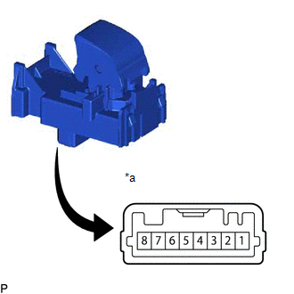
(b) Check that the LED illuminates.
(1) Apply auxiliary battery voltage to the power window regulator switch assembly and check that the LED illuminates.
OK:
| Battery Connection | Specified Condition |
|---|---|
| Auxiliary battery positive (+) → 2 Auxiliary battery negative (-) → 7 | LED illuminates |
If the result is not as specified, replace the power window regulator switch assembly.
READ NEXT:
 Precaution
PRECAUTION PRECAUTION FOR DISCONNECTING CABLE FROM NEGATIVE BATTERY TERMINAL NOTICE: When disconnecting the cable from the negative (-) battery terminal, initialize the following systems after the cab
Parts Location
PARTS LOCATION ILLUSTRATION *1 MAIN BODY ECU (MULTIPLEX NETWORK BODY ECU) *2 COMBINATION METER ASSEMBLY *3 DLC3 *4 CERTIFICATION ECU (SMART KEY ECU ASSEMBLY) *5 INSTRUMENT PA
SEE MORE:
Removal
REMOVAL CAUTION / NOTICE / HINT The necessary procedures (adjustment, calibration, initialization or registration) that must be performed after parts are removed and installed, or replaced during transmission control cable assembly removal/installation are shown below. Necessary Procedures After Par
Hybrid Generator Circuit Current Out of Range (P1CA51D)
DTC SUMMARY MALFUNCTION DESCRIPTION This DTC indicates that current does not flow as commanded due to a generator output circuit malfunction. The cause of this malfunction may be one of the following: Area Main Malfunction Description Inside of inverter Inverter with converter assembly in
