Lexus ES: Parts Location
PARTS LOCATION
ILLUSTRATION
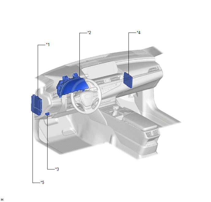
| *1 | MAIN BODY ECU (MULTIPLEX NETWORK BODY ECU) | *2 | COMBINATION METER ASSEMBLY |
| *3 | DLC3 | *4 | CERTIFICATION ECU (SMART KEY ECU ASSEMBLY) |
| *5 | INSTRUMENT PANEL JUNCTION BLOCK ASSEMBLY - ECU-B NO. 2 FUSE - DOOR F/L FUSE - DOOR F/R FUSE - DOOR R/L FUSE - DOOR R/R FUSE | - | - |
ILLUSTRATION
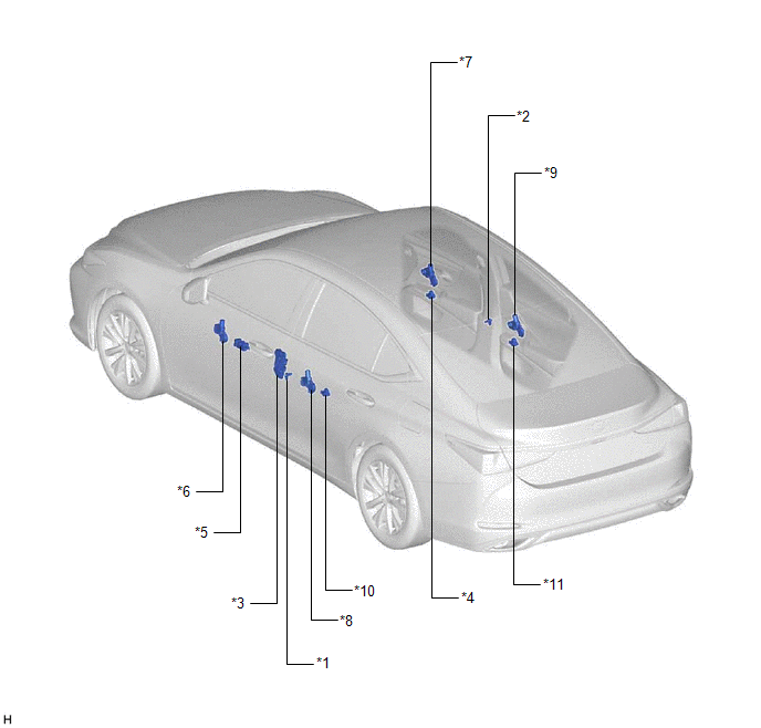
| *1 | FRONT DOOR COURTESY LIGHT SWITCH ASSEMBLY (for LH) | *2 | FRONT DOOR COURTESY LIGHT SWITCH ASSEMBLY (for RH) |
| *3 | FRONT DOOR LOCK WITH MOTOR ASSEMBLY LH | *4 | POWER WINDOW REGULATOR SWITCH ASSEMBLY |
| *5 | MULTIPLEX NETWORK MASTER SWITCH ASSEMBLY | *6 | POWER WINDOW REGULATOR MOTOR ASSEMBLY (for Driver Door) |
| *7 | POWER WINDOW REGULATOR MOTOR ASSEMBLY (for Front Passenger Door) | *8 | POWER WINDOW REGULATOR MOTOR ASSEMBLY (for Rear LH Door) |
| *9 | POWER WINDOW REGULATOR MOTOR ASSEMBLY (for Rear RH Door) | *10 | REAR POWER WINDOW REGULATOR SWITCH ASSEMBLY (for LH Door) |
| *11 | REAR POWER WINDOW REGULATOR SWITCH ASSEMBLY (for RH Door) | - | - |
READ NEXT:
 System Diagram
SYSTEM DIAGRAM Communication Table Transmitting ECU Receiving ECU Signal Communication Method Multiplex Network Master Switch Assembly Power Window Regulator Motor Assembly (for Driv
System Description
SYSTEM DESCRIPTION POWER WINDOW CONTROL SYSTEM DESCRIPTION (a) The power window control system controls the power window operation using the power window regulator motor assemblies. The main controls
How To Proceed With Troubleshooting
CAUTION / NOTICE / HINT HINT:
Use the following procedure to troubleshoot the power window control system.
*: Use the Techstream.
PROCEDURE 1. VEHICLE BROUGHT TO WORKSHOP
NEXT
SEE MORE:
Steering Angle Midpoint Initial Setting Incomplete (C1AEA)
DESCRIPTION When the clearance warning ECU assembly detects that the steering angle neutral point memorization is incomplete during self diagnosis, C1AEA is stored. DTC No. Detection Item DTC Detection Condition Trouble Area C1AEA Steering Angle Midpoint Initial Setting Incomplete S
Removal
REMOVAL CAUTION / NOTICE / HINT HINT:
Use the same procedure for the RH side and LH side.
The following procedure is for the LH side.
PROCEDURE 1. REMOVE NO. 2 DOOR TRIM PAD Click here 2. REMOVE MULTIPLEX NETWORK MASTER SWITCH ASSEMBLY WITH FRONT DOOR UPPER ARMREST BASE PANEL (for Driver
