
Lexus ES: Emergency Call Switch Circuit Short to Ground (B15C511,B15C513)
DESCRIPTION
If the DCM (telematics transceiver) detects an error in the communication between the DCM (telematics transceiver) and the map light sub-assembly (manual (SOS) switch) as a result of the DCM (telematics transceiver) self check, this DTC will be stored.
| DTC No. | Detection Item | DTC Detection Condition | Trouble Area |
|---|---|---|---|
| B15C511 | Emergency Call Switch Circuit Short to Ground | Manual (SOS) switch impedance (Ω) is lower than the malfunction threshold for 10 seconds or more when the power switch is on (IG) |
|
| B15C513 | Emergency Call Switch Circuit Open | Manual (SOS) switch impedance (Ω) is higher than the malfunction threshold for 10 seconds or more when the power switch is on (IG) |
|
WIRING DIAGRAM
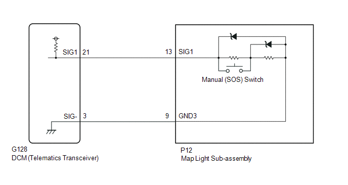
CAUTION / NOTICE / HINT
NOTICE:
Depending on the parts that are replaced during vehicle inspection or maintenance, performing initialization, registration or calibration may be needed. Refer to Precaution for Safety Connect System.
Click here .gif)
PROCEDURE
| 1. | CHECK DTC |
(a) Turn the power switch off.
(b) Connect the Techstream to the DLC3.
(c) Turn the power switch on (IG) and wait for 10 seconds or more.
(d) Turn the Techstream on.
(e) Clear the DTCs.
Body Electrical > Telematics > Clear DTCs(f) Check for DTCs and check that no DTCs are output.
Body Electrical > Telematics > Trouble CodesOK:
No DTCs are output.
| OK |  | USE SIMULATION METHOD TO CHECK |
|

| 2. | INSPECT MAP LIGHT SUB-ASSEMBLY (MANUAL (SOS) SWITCH) |
| (a) Remove the map light sub-assembly (manual (SOS) switch). Click here |
|
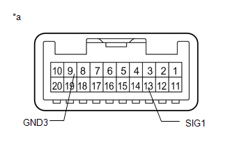
(b) Measure the resistance according to the value(s) in the table below.
Standard Resistance:
| Tester Connection | Condition | Specified Condition |
|---|---|---|
| 13 (SIG1) - 9 (GND3) | Manual (SOS) switch not operated | 410 to 414 Ω |
| 13 (SIG1) - 9 (GND3) | Manual (SOS) switch operated | 81 to 83 Ω |
| NG | | REPLACE MAP LIGHT SUB-ASSEMBLY (MANUAL (SOS) SWITCH) |
|
| 3. | CHECK HARNESS AND CONNECTOR (DCM (TELEMATICS TRANSCEIVER) - MAP LIGHT SUB-ASSEMBLY (MANUAL (SOS) SWITCH)) |
(a) Disconnect the G128 DCM (telematics transceiver) connector.
(b) Disconnect the P12 map light sub-assembly (manual (SOS) switch) connector.
(c) Measure the resistance according to the value(s) in the table below.
Standard Resistance:
| Tester Connection | Condition | Specified Condition |
|---|---|---|
| G128-21 (SIG1) - P12-13 (SIG1) | Always | Below 1 Ω |
| G128-3 (SIG-) - P12-9 (GND3) | Always | Below 1 Ω |
| G128-21 (SIG1) or P12-13 (SIG1) - Body ground | Always | 10 kΩ or higher |
| G128-3 (SIG-) or P12-9 (GND3) - Body ground | Always | 10 kΩ or higher |
| NG | | REPAIR OR REPLACE HARNESS OR CONNECTOR |
|
| 4. | REPLACE DCM (TELEMATICS TRANSCEIVER) |
(a) Replace the DCM (telematics transceiver) with a new one.
Click here
NOTICE:
- The power switch must be off.
- Do not exchange the DCM (telematics transceiver) with one from another vehicle.
| NEXT | | PERFORM DCM ACTIVATION |
READ NEXT:
 Telephone Main Antenna Circuit Short to Ground (B15CB11,B15CB13)
DESCRIPTION This DTC is stored when the DCM (telematics transceiver) detects an open or a short in the telephone antenna (main) circuit. DTC No. Detection Item DTC Detection Condition Trouble
Backup Battery Internal Electronic Failure (B15CC49)
DESCRIPTION This DTC is set when the DCM (telematics transceiver) detects one of the following:
The mobilephone battery voltage drops or the mobilephone battery malfunctions.
The mobilephone batt
Telephone Sub Antenna Circuit Short to Ground (B153711,B153713)
DESCRIPTION These DTCs are stored when a malfunction occurs in the telephone and GPS antenna assembly (for Front Side). DTC No. Detection Item DTC Detection Condition Trouble Area B153711
SEE MORE:
Removal
REMOVAL CAUTION / NOTICE / HINT The necessary procedures (adjustment, calibration, initialization, or registration) that must be performed after parts are removed, installed, or replaced during brake booster with master cylinder assembly removal/installation are shown below. Necessary Procedures Aft
Inspection
INSPECTION PROCEDURE 1. INSPECT FUEL PUMP (a) Measure the resistance according to the value(s) in the table below. Standard Resistance: Tester Connection Specified Condition U - V 0.05 to 3.0 Ω V - W 0.05 to 3.0 Ω U - W 0.05 to 3.0 Ω If the result is not as specified
