Lexus ES: Electronic Circuit Inspection Procedure
ELECTRONIC CIRCUIT INSPECTION PROCEDURE
BASIC INSPECTION
(a) WHEN MEASURING RESISTANCE OF ELECTRONIC PARTS
(1) Unless otherwise stated, all resistance measurements are standard values measured at an ambient temperature of 20°C (68°F). Resistance measurements may be inaccurate if measured at high temperatures, i.e. immediately after the vehicle has been running. Measurements should be made after the engine has cooled down.
|
*a |
Incorrect |
|
*b |
Correct |
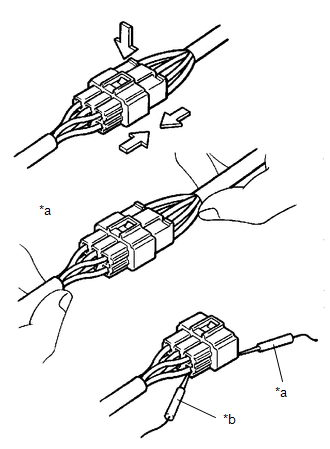
(b) HANDLING CONNECTORS
(1) When disconnecting a connector, first squeeze the mating connector housing halves tightly together to release the lock, and then press the lock claw and separate the connector.
(2) When disconnecting a connector, do not pull on the harnesses. Grasp the connector directly and separate it.
(3) Before connecting a connector, check that there are no deformations, damage, looseness or missing terminals.
(4) When connecting a connector, press firmly until it locks with a "click" sound.
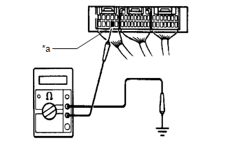
(5) If checking a connector with an electrical tester, check the connector from the backside (harness side) using a mini test lead.
NOTICE:
- As a waterproof connector cannot be checked from the backside, check it by connecting a sub-harness.
- Do not damage the terminals by moving the inserted tester probe (mini test lead)
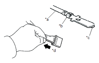
(c) CHECKING CONNECTORS
|
*a |
Core Wire |
|
*b |
Looseness of Crimping |
|
*c |
Terminal Deformation |
|
*d |
Pull Lightly |
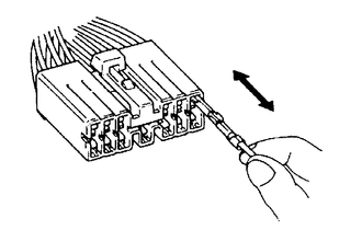
(1) Checking when a connector is connected: Squeeze the connectors together to confirm that they are fully connected and locked.
(2) Checking when a connector is disconnected: Check by pulling the wire harness lightly from the backside of the connector. Look for unlatched terminals, missing terminals, loose crimps or broken conductor wires. Visually check for corrosion, metallic or foreign matter and water, and bent, rusted, overheated, contaminated or deformed terminals.
(3) Checking the contact pressure of the terminal: Prepare a spare male terminal. Insert it into a female terminal, and check for ample tension when inserting and after full engagement.
NOTICE:
When testing a gold-plated female terminal, always use a gold-plated male terminal.
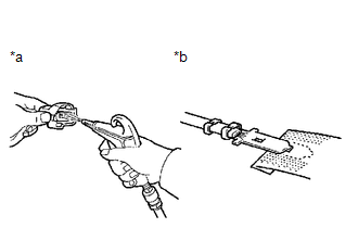
(d) CONNECTOR TERMINAL REPAIR METHOD
|
*a |
Correct |
|
*b |
Incorrect |
(1) If there is any foreign matter on the terminal, clean the contact point with compressed air or a cloth. Never rub the contact point using sandpaper as the plating may come off.
(2) If there is abnormal contact pressure, replace the female terminal. If the male terminal is gold-plated (gold color), use a gold-plated female terminal; if it is silver-plated (silver color), use a silver-plated female terminal.
(3) Damaged, deformed or corroded terminals should be replaced. If the terminal does not lock into the housing, the housing may have to be replaced.
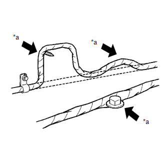
(e) WIRE HARNESS HANDLING
|
*a |
Incorrect |
(1) If removing a wire harness, check the wiring and clamps before proceeding so that it can be restored in the same way.
(2) Never twist, pull or slacken the wire harness more than necessary.
(3) The wire harness should never come into contact with any high temperature, rotating, moving, vibrating or sharp-edged parts. Avoid contact with panel edges, screw tips and other sharp items.
(4) When installing parts, never pinch the wire harness.
(5) Never cut or break the cover of the wire harness. If it is cut or broken, repair it with insulating tape or replace the wire harness.
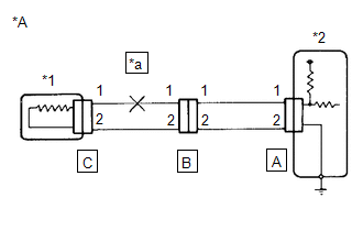
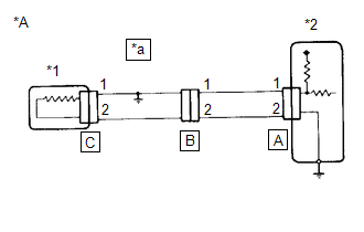
CHECK FOR OPEN CIRCUIT
(a) For an open circuit in the wire harness in Fig. 1, measure the resistance and voltage as follows:
|
*A |
Fig. 1 |
|
*1 |
SENSOR |
|
*2 |
ECU |
|
*a |
OPEN |
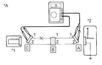
(b) Check the resistance.
(1) Disconnect connectors A and C, and measure the resistance between the terminals of the connectors.
Standard Resistance (Fig. 2):
|
Tester Connection |
Condition |
Specified Condition |
|---|---|---|
|
Connector A terminal 1 - Connector C terminal 1 |
Always |
10 kΩ or higher |
|
Connector A terminal 2 - Connector C terminal 2 |
Always |
Below 1 Ω |
HINT:
Measure the resistance while lightly shaking the wire harness vertically and horizontally.
- If the results match the values specified above, an open circuit exists between terminal 1 of connector A and terminal 1 of connector C.
|
*A |
Fig. 2 |
|
*1 |
SENSOR |
|
*2 |
ECU |
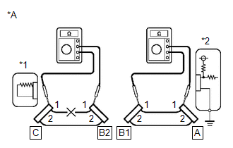
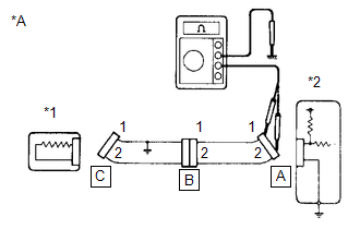
(2) Disconnect connector B and measure the resistance between the terminals of the connectors.
|
*A |
Fig. 3 |
|
*1 |
SENSOR |
|
*2 |
ECU |
Standard Resistance (Fig. 3):
|
Tester Connection |
Condition |
Specified Condition |
|---|---|---|
|
Connector A terminal 1 - Connector B1 terminal 1 |
Always |
Below 1 Ω |
|
Connector B2 terminal 1 - Connector C terminal 1 |
Always |
10 kΩ or higher |
- If the results match the values specified above, an open circuit exists between terminal 1 of connector B2 and terminal 1 of connector C.
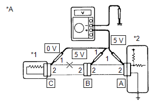
(c) Check the voltage.
|
*A |
Fig. 4 |
|
*1 |
SENSOR |
|
*2 |
ECU |
(1) In a circuit in which voltage is applied to the ECU connector terminal, an open circuit can be checked by conducting a voltage check.
With each connector still connected, measure the voltage between body ground and the following terminals (in this order): 1) terminal 1 of connector A, 2) terminal 1 of connector B, and 3) terminal 1 of connector C.
Standard Voltage (Fig. 4):
|
Tester Connection |
Condition |
Specified Condition |
|---|---|---|
|
Connector A terminal 1 - Body ground |
Ignition switch ON (IG) |
5 V |
|
Connector B terminal 1 - Body ground |
Ignition switch ON (IG) |
5 V |
|
Connector C terminal 1 - Body ground |
Ignition switch ON (IG) |
Below 1 V |
- If the results match the values specified above, an open circuit exists in the wire harness between terminal 1 of connector B and terminal 1 of connector C.
CHECK FOR SHORT CIRCUIT
(a) If a wire in the harness is shorted to ground (Fig. 5), locate the shorted section by measuring the resistance as follows:
|
*A |
Fig. 5 |
|
*1 |
SENSOR |
|
*2 |
ECU |
|
*a |
SHORT |
(b) Check the resistance to body ground.
|
*A |
Fig. 6 |
|
*1 |
SENSOR |
|
*2 |
ECU |
(1) Disconnect connectors A and C, and measure the resistance.
Standard Resistance (Fig. 6):
|
Tester Connection |
Condition |
Specified Condition |
|---|---|---|
|
Connector A terminal 1 - Body ground |
Always |
Below 1 Ω |
|
Connector A terminal 2 - Body ground |
Always |
10 kΩ or higher |
HINT:
Measure the resistance while lightly shaking the wire harness vertically and horizontally.
- If the results match the values specified above, a short circuit exists between terminal 1 of connector A and terminal 1 of connector C.
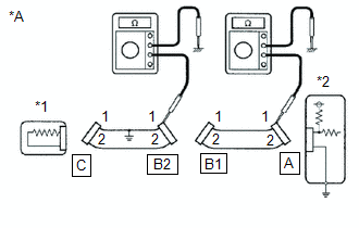
(2) Disconnect connector B and measure the resistance.
|
*A |
Fig. 7 |
|
*1 |
SENSOR |
|
*2 |
ECU |
Standard Resistance (Fig. 7):
|
Tester Connection |
Condition |
Specified Condition |
|---|---|---|
|
Connector A terminal 1 - Body ground |
Always |
10 kΩ or higher |
|
Connector B2 terminal 1 - Body ground |
Always |
Below 1 Ω |
- If the results match the values specified above, a short circuit exists between terminal 1 of connector B2 and terminal 1 of connector C.
CHECK AND REPLACE ECU
NOTICE:
- The connector should not be disconnected from the ECU. Perform the inspection from the backside of the connector on the wire harness side.
- When no measuring condition is specified, perform the inspection with the engine stopped and the ignition switch ON (IG).
- Check that the connectors are fully seated. Check for loose, corroded or broken wires.
(a) First, check the ECU ground circuit. If it is faulty, repair it. If it is normal, the ECU could be faulty. Temporarily replace the ECU with a known good one and check if the problem symptoms occur. If the problem symptoms disappear, replace the original ECU.
(1) Measure the resistance between the ECU ground terminal and body ground.
|
*a |
Ground |
Standard Resistance:
Below 1 Ω
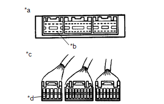
(2) Disconnect the ECU connector. Check the ground terminals on the ECU side and wire harness side for bent terminals, corrosion or foreign matter. Lastly, check the contact pressure of the female terminals.
|
*a |
Component without harness connected (ECU) |
|
*b |
Ground |
|
*c |
Front view of wire harness connector (to ECU) |
|
*d |
Ground |
READ NEXT:
 How To Proceed With Troubleshooting
HOW TO PROCEED WITH TROUBLESHOOTING
OPERATION FLOW
HINT:
Perform troubleshooting in accordance with the procedure below. The following
is an outline of basic troubleshooting procedure. Confirm th
How To Use This Manual
General Information
GENERAL INFORMATION
GENERAL DESCRIPTION
(a) This manual is written in accordance with SAE J2008.
(b) Repair operations can be separated mainly into the following 3 processes:
Identification Information
Vehicle Identification And Serial Numbers
VEHICLE IDENTIFICATION AND SERIAL NUMBERS
VEHICLE IDENTIFICATION NUMBER
(a) The vehicle identification number is stamped on the vehicle body and on the
SEE MORE:
How To Proceed With Troubleshooting
CAUTION / NOTICE / HINT HINT:
Use the following procedure to troubleshoot the sliding roof system.
*: Use the Techstream.
PROCEDURE 1. VEHICLE BROUGHT TO WORKSHOP
NEXT 2. CUSTOMER PROBLEM ANALYSIS HINT:
In troubleshooting, confirm that the problem sympto
Installation
INSTALLATION PROCEDURE 1. INSTALL WATER INLET WITH THERMOSTAT SUB-ASSEMBLY (a) Install a new gasket to the water inlet with thermostat sub-assembly. (b) Install the water inlet with thermostat sub-assembly with the 2 bolts and 2 nuts. Torque: 10 N·m {102 kgf·cm, 7 ft·lbf} 2. CONNECT WATER BY-PAS
