Lexus ES: Identification Information
Vehicle Identification And Serial Numbers
VEHICLE IDENTIFICATION AND SERIAL NUMBERS
VEHICLE IDENTIFICATION NUMBER
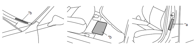
(a) The vehicle identification number is stamped on the vehicle body and on the certification label or name label as shown in the illustration.
|
*a |
Certification Label or Name Label |
*b |
Vehicle Identification Number |
ENGINE SERIAL NUMBER AND TRANSAXLE CODE
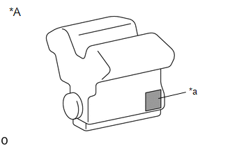
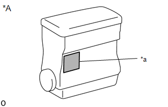
(a) The engine serial number is stamped on the cylinder block of the engine as shown in the illustration.
|
*A |
2GR-FKS |
|
*a |
Engine Serial Number |
|
*A |
A25A-FXS |
|
*a |
Engine Serial Number |
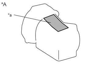
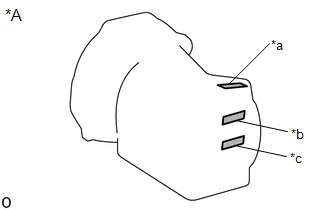
(b) The transaxle code, transaxle type and transaxle serial number are stamped on the transaxle case as shown in the illustration.
|
*A |
UA80E |
|
*a |
Transaxle Serial Number |
|
*A |
P710 |
|
*a |
Transaxle Serial Number |
|
*b |
Transaxle Code |
|
*c |
Transaxle Type |
Vehicle Identification And Serial Numbers
VEHICLE IDENTIFICATION AND SERIAL NUMBERS
VEHICLE IDENTIFICATION NUMBER
(a) The vehicle identification number is stamped on the vehicle body and on the certification label or name label as shown in the illustration.
.png)
|
*a |
Certification Label or Name Label |
*b |
Vehicle Identification Number |
ENGINE SERIAL NUMBER AND TRANSAXLE CODE
(a) The engine serial number is stamped on the cylinder block of the engine as shown in the illustration.
.png)
|
*A |
2GR-FKS |
|
*a |
Engine Serial Number |
.png)
|
*A |
A25A-FKS, A25A-FXS |
|
*a |
Engine Serial Number |
(b) The transaxle code, transaxle type and transaxle serial number are stamped on the transaxle case as shown in the illustration.
.png)
|
*A |
UA80E, UB80F |
|
*a |
Transaxle Serial Number |
.png)
|
*A |
P710 |
|
*a |
Transaxle Serial Number |
|
*b |
Transaxle Code |
|
*c |
Transaxle Type |
READ NEXT:
 Precaution
PRECAUTION
BASIC REPAIR HINT
(a) HINTS ON OPERATIONS
1
Attire
Always wear a clean uniform.
A hat and safety shoes must be worn.
Vehicle Lift And Support Locations
VEHICLE LIFT AND SUPPORT LOCATIONS
PRECAUTIONS ABOUT VEHICLE CONDITION WHEN RAISING VEHICLE
(a) The vehicle must be unloaded before jacking up or raising the vehicle. Never
jack up or raise a heav
SEE MORE:
Data List / Active Test
DATA LIST / ACTIVE TEST DATA LIST NOTICE: In the table below, the values listed under "Normal Condition" are reference values. Do not depend solely on these reference values when deciding whether a part is faulty or not. HINT: Using the Techstream to read the Data List allows the values or states of
Headlight Dimmer Switch Circuit
DESCRIPTION The steering sensor receives the following switch information:
Light control switch in DRL OFF*, tail, head or AUTO position
Dimmer switch in high, low or high flash (pass) position
*: w/ DRL OFF Switch
WIRING DIAGRAM CAUTION / NOTICE / HINT NOTICE: Before replacing the ma
