Lexus ES: ECU Power Source Circuit
DESCRIPTION
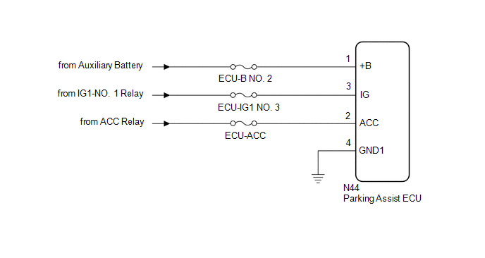
This circuit is the power source circuit to operate the parking assist ECU. The parking assist ECU controls the panoramic view monitor system.
WIRING DIAGRAM
CAUTION / NOTICE / HINT
NOTICE:
Inspect the fuse for circuits related to this system before performing the following inspection procedure.
HINT:
If the parking assist ECU does not operate due to a power source problem, other system DTCs may be stored due to a CAN communication interruption.
PROCEDURE
| 1. | CHECK HARNESS AND CONNECTOR (PARKING ASSIST ECU - BODY GROUND) |
(a) Disconnect the N44 parking assist ECU connector.
(b) Measure the resistance according to the value(s) in the table below.
Standard Resistance:
| Tester Connection | Condition | Specified Condition |
|---|---|---|
| N44-4 (GND1) - Body ground | Always | Below 1 Ω |
| NG | .gif) | REPAIR OR REPLACE HARNESS OR CONNECTOR |
|
.gif)
| 2. | CHECK HARNESS AND CONNECTOR (PARKING ASSIST ECU POWER SOURCE) |
(a) Disconnect the N44 parking assist ECU connector.
(b) Measure the voltage according to the value(s) in the table below.
Standard Voltage:
| Tester Connection | Condition | Specified Condition |
|---|---|---|
| N44-1 (+B) - N44-4 (GND1) | Always | 11 to 14 V |
| N44-2 (ACC) - N44-4 (GND1) | Power switch on (ACC) | 11 to 14 V |
| Power switch off | Below 1 V | |
| N44-3 (IG) - N44-4 (GND1) | Power switch on (IG) | 11 to 14 V |
| Power switch off | Below 1 V |
| OK | | PROCEED TO NEXT SUSPECTED AREA SHOWN IN PROBLEM SYMPTOMS TABLE |
| NG | | REPAIR OR REPLACE HARNESS OR CONNECTOR |
READ NEXT:
 How To Proceed With Troubleshooting
CAUTION / NOTICE / HINT HINT:
Use the following procedure to troubleshoot the panoramic view monitor system.
*: Use the Techstream.
PROCEDURE 1. VEHICLE BROUGHT TO WORKSHOP
NEXT
Image from Camera for Panoramic View Monitor is Abnormal
DESCRIPTION The display signal from each camera is transmitted to the multi-display assembly via the parking assist ECU. WIRING DIAGRAM CAUTION / NOTICE / HINT NOTICE:
When "!" is displayed on th
Initialization
INITIALIZATION INITIALIZE PANORAMIC VIEW MONITOR SYSTEM (a) When "!" is displayed on the multi-display assembly, correct the steering angle neutral point using the following method. (1) Fully turn the
SEE MORE:
Parts Location
PARTS LOCATION ILLUSTRATION *1 PARK/NEUTRAL POSITION SWITCH ASSEMBLY *2 SIDE TURN SIGNAL LIGHT ASSEMBLY LH *3 SIDE TURN SIGNAL LIGHT ASSEMBLY RH *4 HEADLIGHT ASSEMBLY LH - HEADLIGHT ECU SUB-ASSEMBLY LH - HEADLIGHT UNIT ASSEMBLY LH (for TMC Made) - HEADLIGHT CORD LH (for Bulb Type
Hybrid/EV Battery Temperature Sensor "A" Signal Stuck In Range (P0A9B2A,P0AC52A,P0ACA2A,P306562)
DESCRIPTION Refer to the description for DTC P0A9B11. Click here DTC No. Detection Item DTC Detection Condition Trouble Area MIL Warning Indicate P0A9B2A Hybrid/EV Battery Temperature Sensor "A" Signal Stuck In Range The performance of battery temperature sensor 0 is abnormal
