Lexus ES: Image from Camera for Panoramic View Monitor is Abnormal
DESCRIPTION
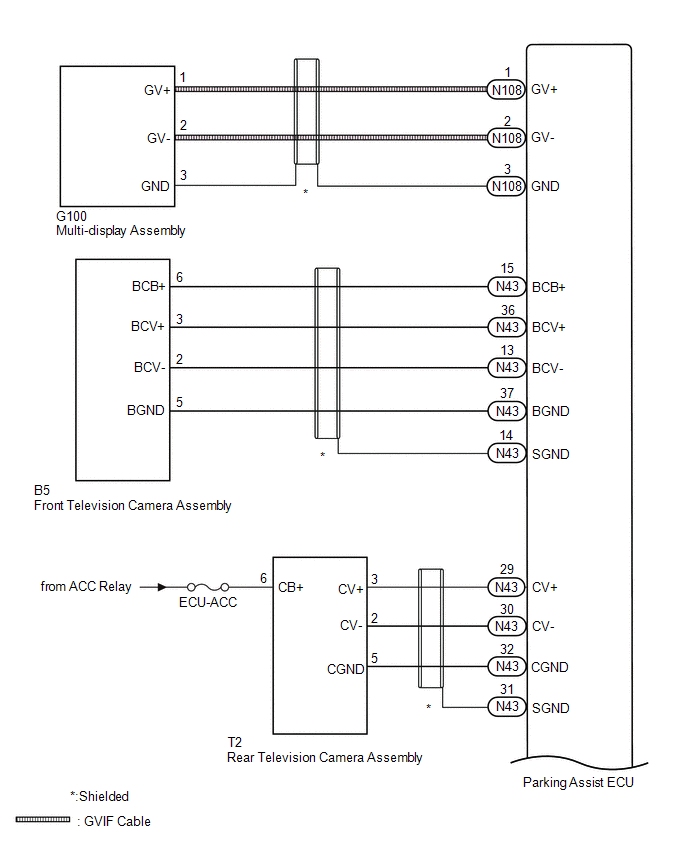
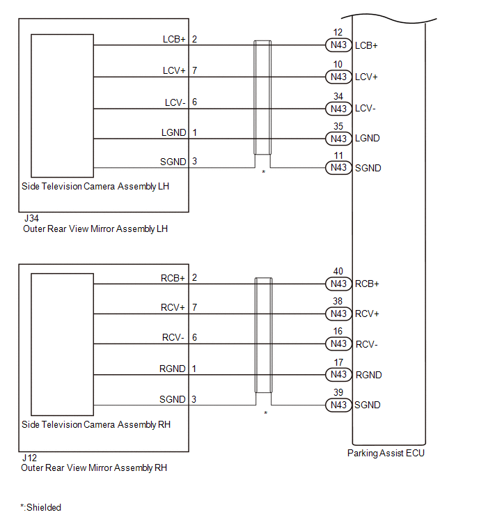
The display signal from each camera is transmitted to the multi-display assembly via the parking assist ECU.
WIRING DIAGRAM
CAUTION / NOTICE / HINT
NOTICE:
-
When "!" is displayed on the multi-display assembly after the cable is disconnected from the negative (-) auxiliary battery terminal, correct the steering angle neutral point.
Click here
.gif)
-
Depending on the parts that are replaced or operations that are performed during vehicle inspection or maintenance, calibration of other systems as well as the panoramic view monitor system may be needed.
Click here
HINT:
Images may be unclear even in normal conditions if:- Electrical devices are used in the cabin (noise may occur in the image).
- The camera lens is frosted over (the image immediately after turning the power switch on (IG) may be blurred or darker than normal).
- The camera lens is dirty with snow, mud, etc.
- A strong beam of light, such as a sunbeam or headlight, hits the camera.
- It is too dark around the camera (at night, etc.).
- The ambient temperature around the camera is either too high or too low.
- The vehicle is tilted at a steep angle.
- The television camera assembly lens is scratched.
- The television camera assembly lens has drops of water on it or the humidity is high.
- When the camera is used under fluorescent lights, sodium lights, or mercury lights, etc., the lights and the illuminated area may appear to flicker.
PROCEDURE
| 1. | CHECK PANORAMIC VIEW MONITOR SYSTEM |
(a) Check if the same malfunction occurs when the panoramic view monitor screen is displayed.
| Result | Proceed to |
|---|---|
| Rear view screen is not displayed. | A |
| Front view screen is not displayed. | B |
| Left side monitor screen is not displayed. | C |
| Right side monitor screen is not displayed. | D |
| Panoramic view monitor screen is not displayed. | E |
| B |  | GO TO STEP 6 |
| C | | GO TO STEP 10 |
| D | | GO TO STEP 15 |
| E | | GO TO STEP 20 |
|

| 2. | CHECK HARNESS AND CONNECTOR (PARKING ASSIST ECU - REAR TELEVISION CAMERA ASSEMBLY) |
Click here
| NG | | REPAIR OR REPLACE HARNESS OR CONNECTOR |
|
| 3. | CHECK HARNESS AND CONNECTOR (ACC POWER SUPPLY - GROUND) |
Click here
| NG | | REPLACE PARKING ASSIST ECU |
|
| 4. | CHECK PARKING ASSIST ECU (CV-, CGND) |
Click here
| NG | | REPLACE PARKING ASSIST ECU |
|
| 5. | CHECK REAR TELEVISION CAMERA ASSEMBLY (CV+, CGND) |
Click here
| OK | | REPLACE PARKING ASSIST ECU |
| NG | | REPLACE REAR TELEVISION CAMERA ASSEMBLY |
| 6. | CHECK HARNESS AND CONNECTOR (PARKING ASSIST ECU - FRONT TELEVISION CAMERA ASSEMBLY) |
Click here
| NG | | REPAIR OR REPLACE HARNESS OR CONNECTOR |
|
| 7. | CHECK PARKING ASSIST ECU (BCV-, BGND) |
Click here
| OK | | REPLACE PARKING ASSIST ECU |
|
| 8. | CHECK PARKING ASSIST ECU (BCB+, BGND) |
Click here
| NG | | REPLACE PARKING ASSIST ECU |
|
| 9. | CHECK FRONT TELEVISION CAMERA ASSEMBLY (BCV+, BGND) |
Click here
| OK | | REPLACE PARKING ASSIST ECU |
| NG | | REPLACE FRONT TELEVISION CAMERA ASSEMBLY |
| 10. | CHECK HARNESS AND CONNECTOR (PARKING ASSIST ECU - OUTER REAR VIEW MIRROR ASSEMBLY LH) |
Click here
| NG | | REPAIR OR REPLACE HARNESS OR CONNECTOR |
|
| 11. | CHECK PARKING ASSIST ECU (LCV-, LGND) |
Click here
| NG | | REPLACE PARKING ASSIST ECU |
|
| 12. | CHECK PARKING ASSIST ECU (LCB+, LGND) |
Click here
| NG | | REPLACE PARKING ASSIST ECU |
|
| 13. | CHECK SIDE TELEVISION CAMERA ASSEMBLY LH (LCV+, LGND) |
Click here
| OK | | REPLACE PARKING ASSIST ECU |
|
| 14. | CHECK SIDE TELEVISION CAMERA ASSEMBLY RH |
(a) Replace the side television camera assembly LH with a new or normally functioning one.
Click here
(b) Check if the same malfunction reoccurs when the side monitor screen is displayed.
| Result | Proceed to |
|---|---|
| Malfunction does not reoccur (returns to normal) | A |
| Malfunction reoccurs | B |
| A | | END (SIDE TELEVISION CAMERA ASSEMBLY LH WAS DEFECTIVE) |
| B | | REPLACE OUTER REAR VIEW MIRROR ASSEMBLY LH |
| 15. | CHECK HARNESS AND CONNECTOR (PARKING ASSIST ECU - OUTER REAR VIEW MIRROR ASSEMBLY RH) |
Click here
| NG | | REPAIR OR REPLACE HARNESS OR CONNECTOR |
|
| 16. | CHECK PARKING ASSIST ECU (RCV-, RGND) |
Click here
| NG | | REPLACE PARKING ASSIST ECU |
|
| 17. | CHECK PARKING ASSIST ECU (RCB+, RGND) |
Click here
| NG | | REPLACE PARKING ASSIST ECU |
|
| 18. | CHECK SIDE TELEVISION CAMERA ASSEMBLY RH (RCV+, RGND) |
Click here
| OK | | REPLACE PARKING ASSIST ECU |
|
| 19. | CHECK SIDE TELEVISION CAMERA ASSEMBLY RH |
(a) Replace the side television camera assembly RH with a new or normally functioning one.
Click here
(b) Check if the same malfunction reoccurs when the side monitor screen is displayed.
| Result | Proceed to |
|---|---|
| Malfunction does not reoccur (returns to normal) | A |
| Malfunction reoccurs | B |
| A | | END (SIDE TELEVISION CAMERA ASSEMBLY RH WAS DEFECTIVE) |
| B | | REPLACE OUTER REAR VIEW MIRROR ASSEMBLY RH |
| 20. | CHECK HARNESS AND CONNECTOR (GVIF CABLE) |
(a) Replace the GVIF cable with a new or normally functioning one.
(b) Check if the same malfunction reoccurs when the panoramic view monitor screen is displayed.
OK:
Malfunction does not reoccur (returns to normal).
| OK | | END (GVIF CABLE IS DEFECTIVE) |
|
| 21. | CHECK MULTI-DISPLAY ASSEMBLY |
(a) Replace the multi-display assembly with a new or normally functioning one.
Click here
(b) Check if the same malfunction reoccurs when the panoramic view monitor screen is displayed.
OK:
Malfunction does not reoccur (returns to normal).
| OK | | END (MULTI-DISPLAY ASSEMBLY) |
| NG | | REPLACE PARKING ASSIST ECU |
READ NEXT:
 Initialization
INITIALIZATION INITIALIZE PANORAMIC VIEW MONITOR SYSTEM (a) When "!" is displayed on the multi-display assembly, correct the steering angle neutral point using the following method. (1) Fully turn the
Parts Location
PARTS LOCATION ILLUSTRATION *1 FRONT TELEVISION CAMERA ASSEMBLY *2 SIDE TELEVISION CAMERA ASSEMBLY RH *3 SIDE TELEVISION CAMERA ASSEMBLY LH *4 BRAKE BOOSTER WITH MASTER CYLINDER AS
Precaution
PRECAUTION PRECAUTION FOR DISCONNECTING CABLE FROM NEGATIVE AUXILIARY BATTERY TERMINAL NOTICE: When disconnecting the cable from the negative (-) auxiliary battery terminal, initialize the following s
SEE MORE:
Components
COMPONENTS ILLUSTRATION *A w/ Stud Bolt - - *1 CONNECTING ROD BEARING *2 CRANKSHAFT *3 CRANKSHAFT BEARING *4 CRANKSHAFT THRUST WASHER SET *5 CYLINDER BLOCK SUB-ASSEMBLY *6 NO. 1 OIL NOZZLE SUB-ASSEMBLY *7 PISTON *8 PISTON RING SET *9 STUD BOLT
Front Camera Response Malfunction (C2A6D)
DESCRIPTION During self diagnosis of the parking assist ECU, the parking assist ECU sends display mode ID signals to the front television camera assembly. This DTC is stored when the output of the front television camera assembly does not match the expected output. DTC No. Detection Item DTC
