
Lexus ES: Drive Motor "A" Inverter Actuator Stuck Closed (P0A7873)
DTC SUMMARY
MALFUNCTION DESCRIPTION
This DTC is stored when a short is detected in the inverter with converter assembly (motor inverter) or the hybrid vehicle transaxle assembly (motor (MG2)). The cause of this malfunction may be one of the following:
- Motor inverter internal circuit malfunction
- Open or short circuit
- Iron particles or damage from foreign objects
DESCRIPTION
For a description of the inverter.
Click here .gif)
| DTC No. | Detection Item | DTC Detection Condition | Trouble Area | MIL | Warning Indicate |
|---|---|---|---|---|---|
| P0A7873 | Drive Motor "A" Inverter Actuator Stuck Closed | Current flow to any phase of the motor (MG2) exceeds the threshold after the motor inverter is shut down due to a DTC indicating a motor inverter malfunction (overheating, overcurrent or circuit malfunction) being stored. (1 trip detection logic) |
| Comes on | Master Warning Light: Comes on |
MONITOR DESCRIPTION
The motor generator control ECU monitors the motor inverter electric current. If the current exceeds the threshold for a specified period of time, the motor generator control ECU will illuminate the MIL and set a DTC.
MONITOR STRATEGY
| Related DTCs | P0A78 (INF P0A7873): MFIV detection (Short circuit malfunction) |
| Required sensors/components | Motor inverter |
| Frequency of operation | Continuous |
| Duration | TMC's intellectual property |
| MIL operation | 1 driving cycle |
| Sequence of operation | None |
TYPICAL ENABLING CONDITIONS
| The monitor will run whenever the following DTCs are not stored | TMC's intellectual property |
| Other conditions belong to TMC's intellectual property | - |
TYPICAL MALFUNCTION THRESHOLDS
| TMC's intellectual property | - |
COMPONENT OPERATING RANGE
| Motor generator control ECU | DTC P0A78 (INF P0A7873) is not detected |
CONFIRMATION DRIVING PATTERN
HINT:
-
After repair has been completed, clear the DTC and then check that the vehicle has returned to normal by performing the following All Readiness check procedure.
Click here
-
When clearing the permanent DTCs, refer to the "CLEAR PERMANENT DTC" procedure.
Click here
- Connect the Techstream to the DLC3.
- Turn the power switch on (IG) and turn the Techstream on.
- Clear the DTCs (even if no DTCs are stored, perform the clear DTC procedure).
- Turn the power switch off and wait for 2 minutes or more.
- Turn the power switch on (IG) and turn the Techstream on.
- With power switch on (IG) and wait for 5 seconds or more. [*1]
- Turn the power switch on (READY) and wait for 5 seconds or more. [*2]
-
Drive the vehicle for approximately 10 minutes mainly using the engine. [*3]
NOTICE:
As the state of charge of the HV battery may be low after driving in fail-safe mode, it will automatically be charged for 5 to 10 minutes with power switch on (READY) after repairs have been performed.
HINT:
[*1] to [*3]: Normal judgment procedure.
The normal judgment procedure is used to complete DTC judgment and also used when clearing permanent DTCs.
- Enter the following menus: Powertrain / Motor Generator / Utility / All Readiness.
-
Check the DTC judgment result.
HINT:
- If the judgment result shows NORMAL, the system is normal.
- If the judgment result shows ABNORMAL, the system has a malfunction.
- If the judgment result shows INCOMPLETE or N/A, perform the normal judgment procedure again.
WIRING DIAGRAM
Refer to the wiring diagram for the Motor High-voltage Circuit.
Click here
CAUTION / NOTICE / HINT
CAUTION:
.png)
-
Before the following operations are conducted, take precautions to prevent electric shock by turning the power switch off, wearing insulated gloves, and removing the service plug grip from HV battery.
- Inspecting the high-voltage system
- Disconnecting the low voltage connector of the inverter with converter assembly
- Disconnecting the low voltage connector of the HV battery
-
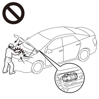
To prevent electric shock, make sure to remove the service plug grip to cut off the high voltage circuit before servicing the vehicle.
-
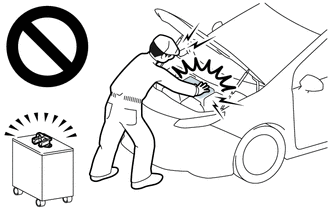
After removing the service plug grip from the HV battery, put it in your pocket to prevent other technicians from accidentally reconnecting it while you are working on the high-voltage system.
-
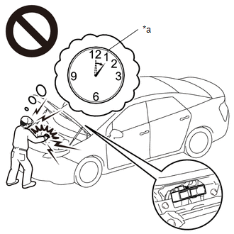
After removing the service plug grip, wait for at least 10 minutes before touching any of the high-voltage connectors or terminals. After waiting for 10 minutes, check the voltage at the terminals in the inspection point in the inverter with converter assembly. The voltage should be 0 V before beginning work.
Click here
HINT:
Waiting for at least 10 minutes is required to discharge the high-voltage capacitor inside the inverter with converter assembly.
*a
Without waiting for 10 minutes
NOTICE:
-
After turning the power switch off, waiting time may be required before disconnecting the cable from the negative (-) auxiliary battery terminal. Therefore, make sure to read the disconnecting the cable from the negative (-) auxiliary battery terminal notices before proceeding with work.
Click here
- DTC P0A7873 is stored after DTCs P0A789E and/or P1C5D19 are stored. After troubleshooting and repairing the malfunction which caused DTC P0A7873 to be stored, be sure to troubleshoot the other DTCs.
- Depending on the conditions in which the vehicle is being operated when a short circuit occurs in the inverter with converter assembly, the hybrid vehicle transaxle assembly may be affected. As this DTC is stored if a short circuit occurs in the inverter with converter assembly, it is necessary to perform a road test to check the hybrid vehicle transaxle assembly. If problems are found, replace the malfunctioning parts.
- After completing the repair, including the repair of previously output DTCs, drive the vehicle at a speed of approximately 40 km/h (25 mph) for 1 minute and check that DTC P0A9000 is not output. If DTC P0A9000 is output, replace the hybrid vehicle transaxle assembly.
PROCEDURE
| 1. | CHECK DTC OUTPUT (HYBRID CONTROL) |
(a) Connect the Techstream to the DLC3.
(b) Turn the power switch on (IG).
(c) Enter the following menus: Powertrain / Hybrid Control / Trouble Codes.
(d) Check for DTCs.
Powertrain > Hybrid Control > Trouble Codes| Result | Proceed to |
|---|---|
| P0A7873 only is output, or DTCs except the ones in the table below are also output. | A |
| Any of the following DTCs are also output. | B |
| Malfunction Content | Relevant DTC | |
|---|---|---|
| Insulation Malfunction | P1C7C49 | Hybrid/EV Battery Voltage System Isolation (A/C Area) Internal Electronic Failure |
| P1C7D49 | Hybrid/EV Battery Voltage System (Hybrid/EV Battery Area) Insulation Resistance Decreased | |
| P1C7E49 | Hybrid/EV Battery Voltage System Isolation (Transaxle Area) Internal Electronic Failure | |
| P1C7F49 | Hybrid/EV Battery Voltage System Isolation (Direct Current Area) Internal Electronic Failure | |
HINT:
-
P0A7873 may be output as a result of the malfunctions indicated by the DTCs above.
- The chart above is listed in inspection order of priority.
- Check DTCs that are output at the same time by following the listed order. (The main cause of the malfunction can be determined without performing unnecessary inspections.)
(e) Turn the power switch off.
| B | .gif) | GO TO DTC CHART (HYBRID CONTROL SYSTEM) |
|
.gif)
| 2. | CHECK HYBRID VEHICLE TRANSAXLE ASSEMBLY (MOTOR (MG2)) |
CAUTION:
Be sure to wear insulated gloves.
(a) Check that the service plug grip is not installed.
NOTICE:
After removing the service plug grip, do not turn the power switch on (READY), unless instructed by the repair manual because this may cause a malfunction.
(b) Disconnect the motor cable from the hybrid vehicle transaxle assembly.
| (c) Check the motor (MG2) for an interphase short using a milliohmmeter. (1) Using a milliohmmeter, measure the resistance according to the value(s) in the table below. HINT: If the motor (MG2) temperature is high, the resistance will vary greatly from the specification. Therefore, measure the resistance at least 8 hours after the vehicle has been stopped. Standard Resistance:
HINT: To correct the variation of the measured resistance due to temperature, use the following formula to calculate the resistance at 20°C (68° F).
The calculation is based on the following:
|
|
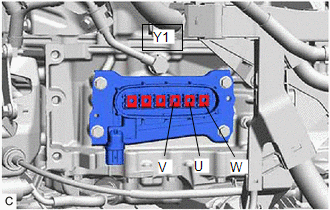
(d) Using a megohmmeter set to 500 V, measure the resistance according to the value(s) in the table below.
NOTICE:
Be sure to set the megohmmeter to 500 V when performing this test. Using a setting higher than 500 V can result in damage to the component being inspected.
Standard Resistance:
| Tester Connection | Condition | Specified Condition |
|---|---|---|
| Y1-1 (W) - Body ground and shield ground | Power switch off | 100 MΩ or higher |
| Y1-2 (U) - Body ground and shield ground | Power switch off | 100 MΩ or higher |
| Y1-3 (V) - Body ground and shield ground | Power switch off | 100 MΩ or higher |
(e) Connect the motor cable.
| NG | | GO TO STEP 5 |
|
| 3. | REPLACE INVERTER WITH CONVERTER ASSEMBLY |
Click here
|
| 4. | REPLACE MOTOR CABLE |
Click here
| NEXT | | GO TO STEP 8 |
| 5. | REPLACE HYBRID VEHICLE TRANSAXLE ASSEMBLY |
Click here
|
| 6. | REPLACE INVERTER WITH CONVERTER ASSEMBLY |
Click here
|
| 7. | REPLACE MOTOR CABLE |
Click here
|
| 8. | CHECK DTC OUTPUT (MOTOR GENERATOR CONTROL SYSTEM) |
(a) Check the other DTCs that were output together with DTC P0A7873.
Powertrain > Motor Generator > Trouble Codes| Relevant DTC | |
|---|---|
| P0A789E | Drive Motor "A" Inverter Stuck On |
| P1C5D19 | Drive Motor "A" Inverter Circuit Current Above Threshold |
NOTICE:
DTC P0A7873 is stored after DTCs P0A789E and/or P1C5D19 are stored. After troubleshooting and repairing the malfunction which caused P0A7873 to be stored, be sure to troubleshoot the other DTCs.
| NEXT | | GO TO DTC CHART (MOTOR GENERATOR CONTROL SYSTEM) |
READ NEXT:
 Generator Inverter Actuator Stuck Open (P0A7A72)
DTC SUMMARY MALFUNCTION DESCRIPTION This DTC indicates that current does not flow as commanded due to a generator output circuit malfunction. The cause of this malfunction may be one of the following:
Generator Inverter Actuator Stuck Closed (P0A7A73)
DTC SUMMARY MALFUNCTION DESCRIPTION This DTC is stored when a short is detected in the inverter with converter assembly (generator inverter) or the hybrid vehicle transaxle assembly (generator (MG1)).
Generator Inverter Stuck On (P0A7A9E,P1C5F19)
DTC SUMMARY MALFUNCTION DESCRIPTION This DTC indicates that a large current flowed in the inverter generator. The cause of this malfunction may be one of the following: Area Main Malfunction Desc
SEE MORE:
Auto Down Operation does not Fully Open Power Window (Catch Protection Function is Activated)
DESCRIPTION If a door glass does not slide smoothly or a power window regulator motor assembly or door window regulator sub-assembly does not operate smoothly, the catch protection function may be triggered automatically, resulting in the auto down operation being unable to fully open the power wind
Removal
REMOVAL CAUTION / NOTICE / HINT The necessary procedures (adjustment, calibration, initialization or registration) that must be performed after parts are removed and installed, or replaced during hybrid battery thermistor removal/installation are shown below. Necessary Procedures After Parts Removed
