Lexus ES: Disassembly
DISASSEMBLY
CAUTION / NOTICE / HINT
The necessary procedures (adjustment, calibration, initialization, or registration) that must be performed after parts are removed and installed, or replaced during front door removal/installation are shown below.
Necessary Procedure After Parts Removed/Installed/Replaced (for Gasoline Model)| Replaced Part or Performed Procedure | Necessary Procedure | Effect/Inoperative Function When Necessary Procedures are not Performed | Link |
|---|---|---|---|
|
*: When performing learning using the Techstream.
Click here | |||
| Disconnect cable from negative battery terminal | Perform steering sensor zero point calibration | Lane Control System | |
| Pre-collision System | |||
| Parking Support Brake System* | |||
| Lighting System | |||
| Memorize steering angle neutral point | Parking Assist Monitor System | | |
| Panoramic View Monitor System | | ||
| Initialize power trunk lid system | Power Trunk Lid System | | |
| Side television camera view adjustment | Panoramic view monitor system | |
| Initialize power window control system |
| |
NOTICE:
- After the engine switch is turned off, the radio receiver assembly records various types of memory and settings. As a result, after turning the engine switch off, make sure to wait at least 85 seconds before disconnecting the cable from the negative (-) battery terminal. (for Audio and Visual System)
- After the engine switch is turned off, the radio receiver assembly records various types of memory and settings. As a result, after turning the engine switch off, make sure to wait at least 85 seconds before disconnecting the cable from the negative (-) battery terminal. (for Navigation System)
| Replaced Part or Performed Procedure | Necessary Procedure | Effect/Inoperative Function When Necessary Procedures are not Performed | Link |
|---|---|---|---|
|
*: When performing learning using the Techstream.
Click here | |||
| Disconnect cable from negative auxiliary battery terminal | Perform steering sensor zero point calibration | Lane Control System | |
| Pre-collision System | |||
| Parking Support Brake System* | |||
| Lighting System | |||
| Memorize steering angle neutral point | Parking Assist Monitor System | | |
| Panoramic View Monitor System | | ||
| Initialize power trunk lid system | Power Trunk Lid System | | |
| Side television camera view adjustment | Panoramic view monitor system | |
| Initialize power window control system |
| |
NOTICE:
- After the power switch is turned off, the radio receiver assembly records various types of memory and settings. As a result, after turning the power switch off, make sure to wait at least 85 seconds before disconnecting the cable from the negative (-) auxiliary battery terminal. (for Audio and Visual System)
- After the power switch is turned off, the radio receiver assembly records various types of memory and settings. As a result, after turning the power switch off, make sure to wait at least 85 seconds before disconnecting the cable from the negative (-) auxiliary battery terminal. (for Navigation System)
HINT:
- Use the same procedure for the RH side and LH side.
- The following procedure is for the LH side.
PROCEDURE
1. PRECAUTION
CAUTION:
Be sure to read Precaution thoroughly before servicing.
for Gasoline Model:
Click here 
for HV Model:
Click here
NOTICE:
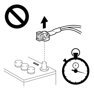
After turning the engine switch (for Gasoline Model) or power switch (for HV Model) off, waiting time may be required before disconnecting the cable from the negative (-) auxiliary battery terminal. Therefore, make sure to read the disconnecting the cable from the negative (-) auxiliary battery terminal notices before proceeding with work.
2. DISCONNECT CABLE FROM NEGATIVE AUXILIARY BATTERY TERMINAL
for 2GR-FKS:
Click here
for A25A-FXS:
Click here
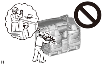
CAUTION:
- Wait at least 90 seconds after disconnecting the cable from the negative (-) auxiliary battery terminal to disable the SRS system.
- If an airbag deploys for any reason, it may cause a serious injury.
3. REMOVE DOOR ARMREST COVER
| (a) Remove the door armrest cover. |
|
4. REMOVE BOX BOTTOM MAT (w/ Illumination)
| (a) Remove the box bottom mat. |
|
5. REMOVE NO. 2 DOOR TRIM PAD
| (a) Using a moulding remover, disengage the 2 claws to remove the No. 2 door trim pad. |
|
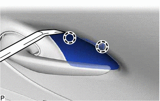
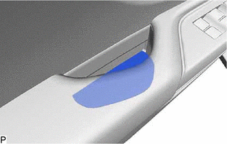
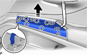
6. REMOVE MULTIPLEX NETWORK MASTER SWITCH ASSEMBLY WITH FRONT DOOR UPPER ARMREST BASE PANEL (for Driver Side)
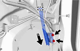
(a) Apply protective tape to the front door trim board sub-assembly as shown in the illustration.
 | Protective Tape |
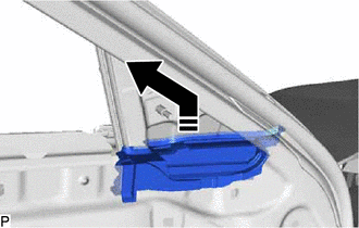
(b) Using a moulding remover, disengage the 2 clips, 5 claws and 3 guides as shown in the illustration.
 | Remove in this Direction |
(c) Disconnect the connector to remove the multiplex network master switch assembly with front door upper armrest base panel.
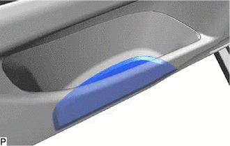
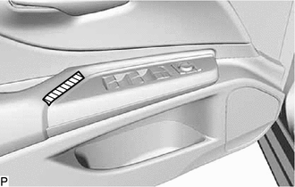
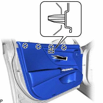
7. REMOVE POWER WINDOW REGULATOR SWITCH ASSEMBLY WITH FRONT DOOR UPPER ARMREST BASE PANEL (for Front Passenger Side)
(a) Apply protective tape to the front door trim board sub-assembly as shown in the illustration.
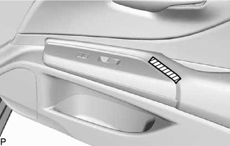
| | Protective Tape |
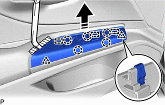
(b) Using a moulding remover, disengage the 2 clips, 5 claws and 4 guides as shown in the illustration.
| | Remove in this Direction |
(c) Disconnect the connector to remove the power window regulator switch assembly with front door upper armrest base panel.
8. REMOVE COURTESY LIGHT ASSEMBLY
Click here
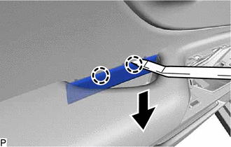
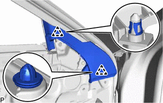
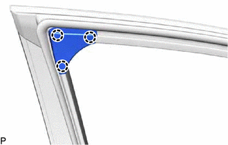
9. REMOVE FRONT DOOR TRIM BOARD SUB-ASSEMBLY
| (a) Using a moulding remover, disengage the 2 claws as shown in the illustration. |
|
| (b) Remove the 3 screws. |
|
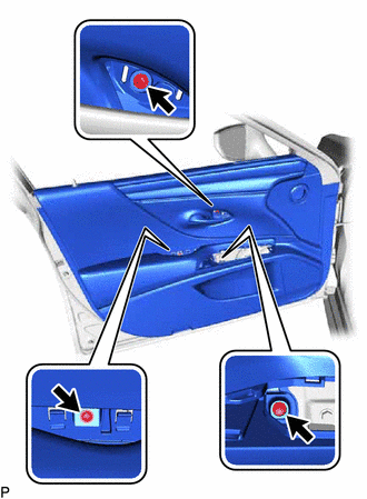
(c) Disengage the 11 clips as shown in the illustration.
 | Place Hand Here |
| | Remove in this Direction |
(d) Disengage the 4 claws and guide as shown in the illustration.
| | Remove in this Direction |
(e) for 17 Speakers:
| (1) Disconnect the connector. |
|
(f) w/ Seat Memory Switch or w/ Illumination:
| (1) Disconnect the connector. |
|
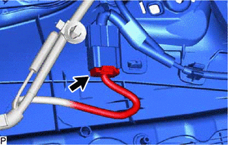
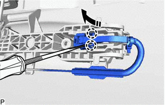
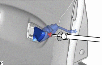
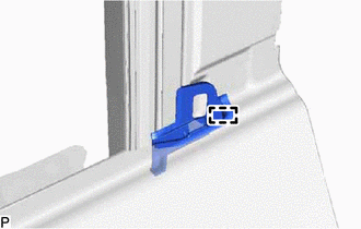
(g) Disconnect the front door lock open lever remote control cable as shown in the illustration.
| | Remove in this Direction |
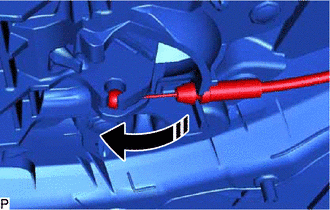
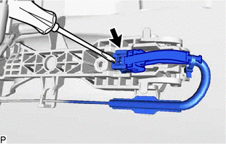
(h) Disengage the 2 claws as shown in the illustration to disconnect the front door inside lock/unlock knob locking cable and remove the front door trim board sub-assembly.
.png) | Push |
| | Remove in this Direction |
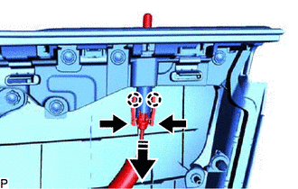
10. REMOVE FRONT DOOR INSIDE HANDLE SUB-ASSEMBLY
| (a) Remove the 3 screws and front door inside handle sub-assembly. |
|
11. REMOVE SEAT MEMORY SWITCH (w/ Seat Memory Switch)
Click here
12. REMOVE FRONT DOOR INSIDE HANDLE ILLUMINATION LIGHT ASSEMBLY (w/ Illumination)
Click here
13. REMOVE FRONT NO. 4 SPEAKER ASSEMBLY (for 17 Speakers)
Click here
14. REMOVE FRONT DOOR WIRE (w/o Illumination)
(a) w/ Seat Memory Switch:
| (1) Using a screwdriver with its tip wrapped with protective tape, disengage the claw. |
|
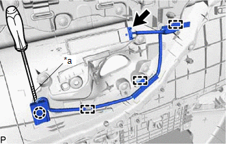
(2) Disengage the 3 clamps.
(3) Disconnect the connector to remove the front door wire.
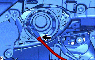
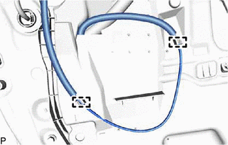
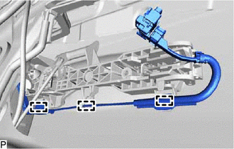
15. REMOVE FRONT DOOR WIRE (w/ Illumination)
| (a) Disengage the clamp. |
|
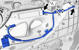
(b) Disconnect each connector to remove the front door wire.
16. REMOVE FRONT DOOR LOWER FRAME BRACKET GARNISH
| (a) Disengage the 2 clips to remove the front door lower frame bracket garnish. |
|
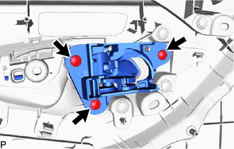
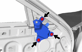
17. REMOVE FRONT DOOR TRIM BRACKET
| (a) Remove the 3 screws and front door trim bracket. |
|
18. REMOVE OUTER MIRROR CONTROL ECU ASSEMBLY (w/ Memory)
Click here
19. REMOVE HOLE PLUG
Click here
20. REMOVE OUTER MIRROR INSTALL HOLE COVER
Click here
21. REMOVE OUTER REAR VIEW MIRROR ASSEMBLY
Click here
22. REMOVE FRONT NO. 1 SPEAKER ASSEMBLY
Click here
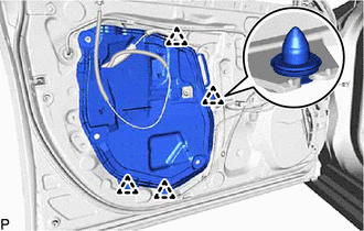
23. REMOVE FRONT DOOR SERVICE HOLE COVER
| (a) Disengage the 2 clamps. |
|
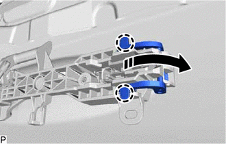
| (b) Turn each front door weatherstrip clip 45 degrees as shown in the illustration and remove the 3 front door weatherstrip clips. |
|
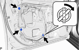
| (c) Disengage the 4 clips to remove the front door service hole cover. |
|
24. REMOVE DOOR SIDE AIRBAG SENSOR
Click here
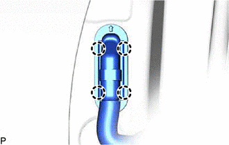
25. REMOVE FRONT DOOR VENT SEAL
| (a) Disengage the 2 clips and disconnect the front door weatherstrip as shown in the illustration. |
|
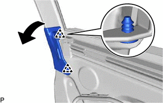
(b) Remove the front door inner glass weatherstrip with front door vent seal as shown in the illustration.
| | Remove in this Direction |
(c) Disengage the 2 guides to remove the front door vent seal from the front door inner glass weatherstrip as shown in the illustration.
| | Remove in this Direction |
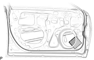
26. REMOVE FRONT DOOR PANEL PROTECTOR
(a) Remove the front door panel protector as shown in the illustration.
| | Remove in this Direction |
27. REMOVE FRONT DOOR GLASS SUB-ASSEMBLY
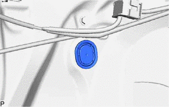
| (a) Remove the hole plug. |
|
(b) for Driver Side:
(1) Connect the multiplex network master switch assembly.
(c) for Front Passenger Side:
(1) Connect the power window regulator switch assembly.
(d) Connect the cable to the negative (-) auxiliary battery terminal.
(e) Turn the engine switch (for Gasoline Model) or power switch (for HV Model) on (IG).
(f) Move the front door glass sub-assembly so that the door glass bolts can be seen.
(g) Turn the engine switch (for Gasoline Model) or power switch (for HV Model) off.
(h) Disconnect the cable from the negative (-) auxiliary battery terminal.
(i) for Driver Side:
(1) Disconnect the multiplex network master switch assembly.
(j) for Front Passenger Side:
(1) Disconnect the power window regulator switch assembly.
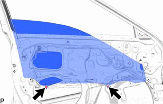
| (k) Remove the 2 bolts. NOTICE: After the bolts are removed, do not allow the front door glass sub-assembly to fall. |
|
(l) Remove the front door glass sub-assembly as shown in the illustration.
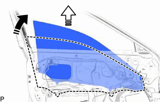
| | Remove in this Direction (1) |
 | Remove in this Direction (2) |
NOTICE:
Do not damage the front door glass sub-assembly.
28. REMOVE FRONT DOOR WINDOW REGULATOR ASSEMBLY
| (a) Disengage the 2 claws to remove the front door No. 2 service hole cover. |
|
| (b) Disconnect the connector. |
|
(c) Loosen the temporary bolt.
NOTICE:
Do not remove the temporary bolt. If the temporary bolt is removed, the front door window regulator assembly may fall and cause damage.
(d) Remove the 5 bolts and front door window regulator assembly.
(e) Remove the temporary bolt from the front door window regulator assembly.
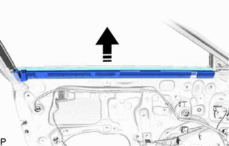
29. REMOVE FRONT DOOR GLASS RUN
| (a) Remove the front door glass run. |
|
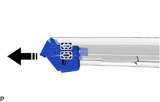
30. REMOVE FRONT DOOR REAR LOWER FRAME SUB-ASSEMBLY
(a) Remove the 2 bolts.
| | Remove in this Direction |
(b) Disengage the guide and remove the front door rear lower frame sub-assembly as shown in the illustration.
31. REMOVE FRONT DOOR FRONT LOWER FRAME SUB-ASSEMBLY
(a) Remove the 2 bolts.
| | Remove in this Direction |
(b) Disengage the guide and remove the front door front lower frame sub-assembly as shown in the illustration.
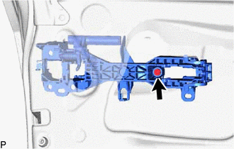
32. REMOVE FRONT DOOR OUTSIDE HANDLE ASSEMBLY
(a) Using a screwdriver, disengage the 2 claws as shown in the illustration.
| | Disengage in this Direction |
| (b) Using a screwdriver, disconnect the connector. |
|
| (c) Disengage the 3 clamps. |
|
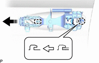
(d) Disengage the 2 claws and move the lever as shown in the illustration.
| | Disengage in this Direction |
(e) Remove the front door outside handle assembly as shown in the illustration.
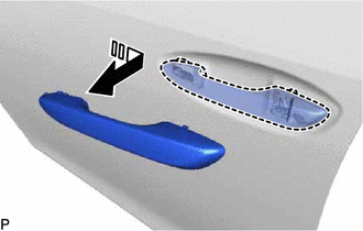
| | Remove in this Direction |
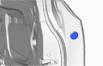
33. REMOVE FRONT DOOR LOCK CYLINDER ASSEMBLY (for Driver Side)
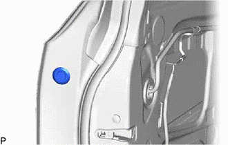
| (a) Remove the hole plug. |
|
| (b) Using a T30 "TORX" socket wrench, loosen the screw and remove the front door lock cylinder assembly. HINT: The screw cannot be removed because it is integrated into the front door outside handle frame sub-assembly. |
|
34. REMOVE FRONT DOOR OUTSIDE HANDLE COVER (for Front Passenger Side)
| (a) Remove the hole plug. |
|
| (b) Using a T30 "TORX" socket wrench, loosen the screw. HINT: The screw cannot be removed because it is integrated into the front door outside handle frame sub-assembly. |
|
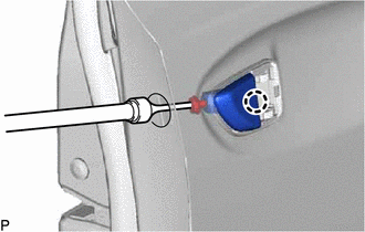
(c) Disengage the claw to remove the front door outside handle cover.
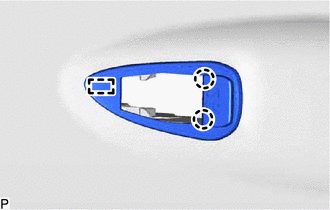
35. REMOVE FRONT DOOR FRONT OUTSIDE HANDLE PAD
| (a) Disengage the 2 claws and guide to remove the front door front outside handle pad. |
|
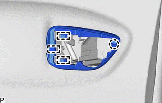
36. REMOVE FRONT DOOR REAR OUTSIDE HANDLE PAD
| (a) Disengage the claw and 3 guides to remove the front door rear outside handle pad. |
|
37. REMOVE FRONT DOOR LOCK WITH MOTOR ASSEMBLY
Click here
38. REMOVE FRONT DOOR OUTSIDE HANDLE FRAME SUB-ASSEMBLY
| (a) Using a T30 "TORX" socket wrench, remove the screw. |
|
(b) Disengage the claw and guide to remove front door outside handle frame sub-assembly as shown in the illustration.
| | Remove in this Direction |
39. REMOVE FRONT DOOR LOCK OPEN ROD
(a) Remove the front door lock open rod as shown in the illustration.
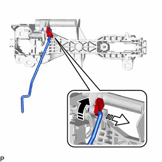
| | Remove in this Direction (1) |
| | Remove in this Direction (2) |
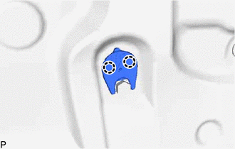
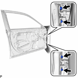
40. REMOVE FRONT DOOR CHECK ASSEMBLY
(a) Remove the 2 nuts, bolt and front door check assembly.
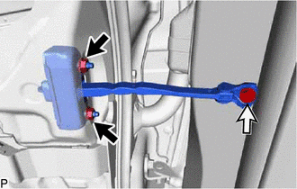
| | Nut |
 | Bolt |
41. REMOVE DOOR UPPER FRAME GARNISH
| (a) Disengage the 3 claws to remove the door upper frame garnish. |
|
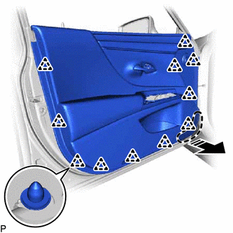
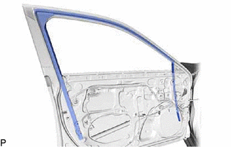
42. REMOVE FRONT DOOR WEATHERSTRIP
(a) Using a clip remover, disengage the 23 clips and remove the front door weatherstrip.
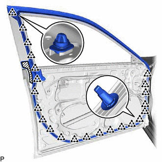
| | Double-sided Tape |
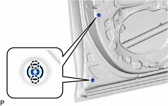
43. REMOVE FRONT DOOR PANEL CUSHION
| (a) Disengage the 4 claws to remove the 2 front door panel cushions. |
|
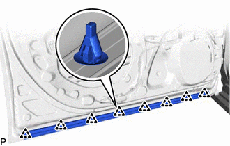
44. REMOVE FRONT DOOR NO. 2 WEATHERSTRIP
| (a) Disengage the 8 clips to remove the front door No. 2 weatherstrip. |
|
45. REMOVE FRONT DOOR FRONT LOWER FRAME UPPER COVER
Click here
46. REMOVE FRONT DOOR BELT MOULDING ASSEMBLY
Click here
47. REMOVE FRONT DOOR REAR WINDOW FRAME MOULDING
Click here
48. REMOVE FRONT DOOR OUTSIDE MOULDING SUB-ASSEMBLY
Click here
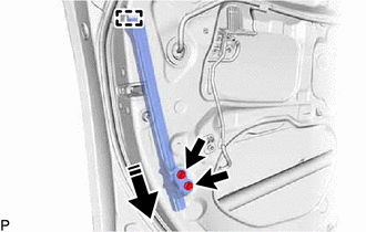
49. REMOVE FRONT DOOR REAR OUTSIDE SEAL
| (a) Disengage the guide to remove the front door rear outside seal. |
|
50. REMOVE FRONT DOOR REAR INNER BLACK OUT TAPE
Click here
51. REMOVE FRONT INNER BLACK OUT TAPE
Click here
52. REMOVE FRONT DOOR SILENCER PAD
| (a) Remove the front door silencer pad. |
|
53. REMOVE FRONT DOOR NO. 3 WEATHERSTRIP
| (a) Disengage the 4 claws to separate the grommet. |
|
(b) Disconnect the connector.
| (c) Remove the 4 bolts and front door panel sub-assembly. NOTICE: To prevent damage, when removing the front door panel sub-assembly, make sure that there are enough people available to hold it securely. |
|
| (d) Remove the 4 clips and front door No. 3 weatherstrip. |
|

READ NEXT:
 Adjustment
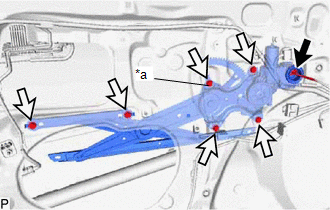
ADJUSTMENT CAUTION / NOTICE / HINT *a Centering Bolt *b Standard Bolt HINT:
Use the same procedure for the RH side and LH side.
The following procedure is for the LH side.
Center
Reassembly
REASSEMBLY CAUTION / NOTICE / HINT HINT:
Use the same procedure for the RH side and LH side.
The following procedure is for the LH side.
PROCEDURE 1. PRECAUTION NOTICE: After turning the engin
Reassembly
REASSEMBLY CAUTION / NOTICE / HINT HINT:
Use the same procedure for the RH side and LH side.
The following procedure is for the LH side.
PROCEDURE 1. PRECAUTION NOTICE: After turning the engin
SEE MORE:
Door Mirror ECU RH Communication Stop Mode
DESCRIPTION Detection Item Symptom Trouble Area Door Mirror ECU RH Communication Stop Mode Any of the following conditions are met:
Communication stop for "Front Door RH/R-Mirror (FR-Door/R-Mirror)" is indicated on the "Communication Bus Check" screen of the Techstream.
Click here
Lost Communication with Humidity/Rain Sensor LIN (B1279)
DESCRIPTION The main body ECU (multiplex network body ECU) and rain sensor communicate via LIN communication. The main body ECU (multiplex network body ECU) stores this DTC if communication becomes abnormal. DTC No. Detection Item DTC Detection Condition Trouble Area Memory DTC Output f
