Lexus ES: Disassembly
DISASSEMBLY
CAUTION / NOTICE / HINT
NOTICE:
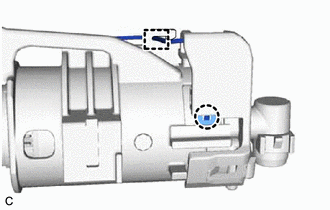
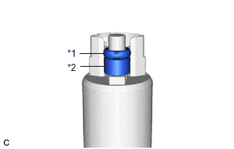
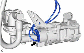
Do not disconnect the tube shown in the illustration when disassembling the fuel suction tube with pump and gauge assembly. Doing so will cause reassembly of the fuel suction tube with pump and gauge assembly to be impossible as the tube is pressed into the fuel suction plate sub-assembly.
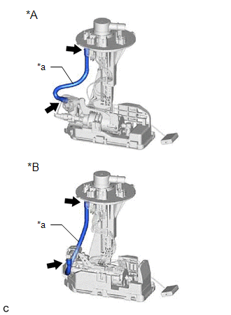
| *A | for Type A |
| *B | for Type B |
| *a | Tube |
PROCEDURE
1. REMOVE FUEL SENDER GAUGE ASSEMBLY
Click here .gif)
2. REMOVE FUEL PUMP
(a) for Type A:
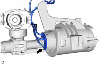
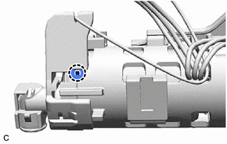
| (1) Disengage the clamp to disconnect the fuel pump harness from the fuel suction plate sub-assembly. NOTICE:
|
|
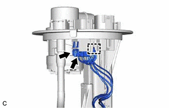
(2) Disconnect the 2 fuel pump harness connectors.
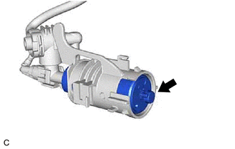
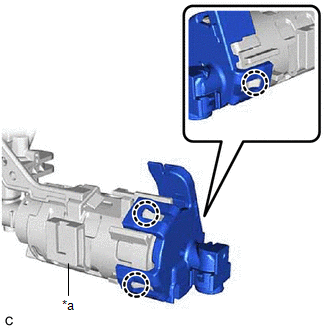
(3) Disengage the claw and slide the fuel suction plate sub-assembly and then separate it from the fuel sub-tank sub-assembly.
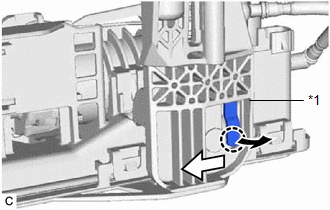
| *1 | Fuel Suction Plate Sub-assembly |
.png) | Pull |
.png) | Slide |
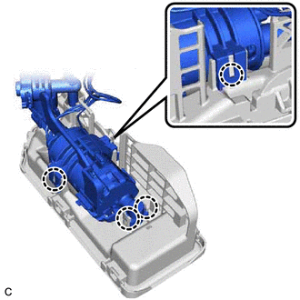
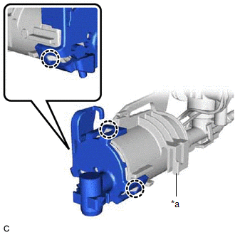
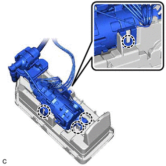
| (4) Disengage the 4 claws and remove the fuel suction plate sub-assembly from the fuel sub-tank sub-assembly. |
|
| (5) Disengage the claw and clamp, and disconnect the fuel pump harness. |
|
| (6) Disconnect the fuel pump harness connector. |
|
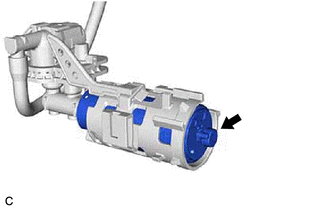
| (7) Disengage the 3 claws and remove the No. 2 fuel suction support from the fuel tube supporter. |
|
| (8) Remove the fuel pump from the fuel tube supporter. |
|
| (9) Remove the O-ring and fuel pump spacer from the fuel pump. |
|
(b) for Type B:
| (1) Disengage the clamp to disconnect the fuel pump harness from the fuel suction plate sub-assembly. NOTICE:
|
|
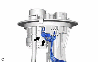
(2) Disconnect the 2 fuel pump harness connectors.
(3) Disengage the claw and slide the fuel suction plate sub-assembly and then separate it from the fuel sub-tank sub-assembly.
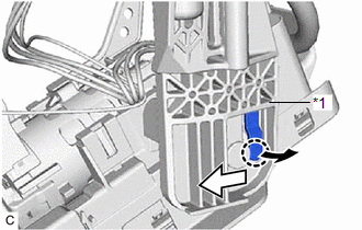
| *1 | Fuel Suction Plate Sub-assembly |
| | Pull |
| | Slide |
| (4) Disengage the 4 claws and remove the fuel suction plate sub-assembly from the fuel sub-tank sub-assembly. |
|
| (5) Disengage the claw and disconnect the fuel pump harness. |
|
| (6) Disconnect the fuel pump harness connector. |
|
| (7) Disengage the 3 claws and remove the No. 2 fuel suction support from the fuel tube supporter. |
|
| (8) Remove the fuel pump from the fuel tube supporter. |
|
| (9) Remove the O-ring and fuel pump spacer from the fuel pump. |
|
READ NEXT:
 Inspection
INSPECTION PROCEDURE 1. INSPECT FUEL PUMP (a) Measure the resistance according to the value(s) in the table below. Standard Resistance: Tester Connection Specified Condition U - V 0.05
Reassembly
REASSEMBLY PROCEDURE 1. INSTALL FUEL PUMP HINT: Perform "Inspection After Repair" after replacing the fuel pump. Click here (a) for Type A: (1) Apply gasoline to a new O-ring. Then install the
Installation
INSTALLATION PROCEDURE 1. INSTALL FUEL SUCTION TUBE WITH PUMP AND GAUGE ASSEMBLY (a) Install a new fuel suction tube set gasket to the fuel tank assembly. (b) Insert the fuel suction tube with pump
SEE MORE:
Engine Oil Pressure Control Circuit Open (P06DA13)
DESCRIPTION Refer to DTC P052477. Click here DTC No. Detection Item DTC Detection Condition Trouble Area MIL Memory Note P06DA13 Engine Oil Pressure Control Circuit Open Open or short in oil pressure control valve assembly circuit (1 trip detection logic).
Open or sho
ABS Operates Before Necessary When Braking
DESCRIPTION Troubleshooting for when ABS operates too soon due to a noisy signal from the speed sensor, a difference in output, etc. CAUTION / NOTICE / HINT NOTICE:
After replacing or removing and installing a speed sensor, perform Dealer Mode (Signal Check) inspection to confirm that the speed s
