Lexus ES: Disassembly
DISASSEMBLY
CAUTION / NOTICE / HINT
NOTICE:
This procedure includes the removal of small-head bolts. Refer to Small-Head Bolts of Basic Repair Hint to identify the small-head bolts.
Click here .gif)
PROCEDURE
1. REMOVE SPARK PLUG
Click here
2. REMOVE KNOCK CONTROL SENSOR
Click here
3. REMOVE ENGINE COOLANT TEMPERATURE SENSOR
Click here
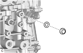
4. REMOVE STRAIGHT SCREW PLUG
| (a) Remove the straight screw plug and gasket from the cylinder block sub-assembly. |
|
5. REMOVE OIL PRESSURE AND TEMPERATURE SENSOR
Click here
6. REMOVE OIL PRESSURE CONTROL VALVE ASSEMBLY
Click here
7. REMOVE CAMSHAFT POSITION SENSOR (for Intake Side)
Click here
8. REMOVE CAMSHAFT POSITION SENSOR (for Exhaust Side)
Click here
9. REMOVE CAM TIMING OIL CONTROL SOLENOID ASSEMBLY
Click here
10. REMOVE O-RING
Click here
11. REMOVE CAM TIMING CONTROL MOTOR WITH EDU ASSEMBLY
Click here
12. REMOVE CAM TIMING CONTROL MOTOR O-RING
Click here
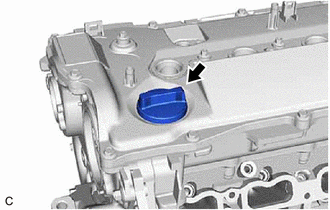
13. REMOVE OIL FILLER CAP ASSEMBLY
| (a) Remove the oil filler cap assembly from the cylinder head cover sub-assembly. |
|
14. REMOVE OIL FILLER CAP GASKET
| (a) Remove the oil filler cap gasket from the oil filler cap assembly. |
|
.png)
15. REMOVE CRANKSHAFT POSITION SENSOR
Click here
16. REMOVE PCV VALVE (VENTILATION VALVE SUB-ASSEMBLY)
Click here
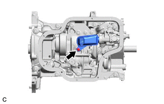
17. REMOVE VACUUM PUMP ASSEMBLY
Click here
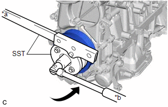
18. REMOVE CRANKSHAFT PULLEY ASSEMBLY
| (a) Using SST, hold the crankshaft pulley assembly and loosen the crankshaft pulley bolt. Further loosen the crankshaft pulley bolt until 2 or 3 threads remain screwed into the crankshaft. SST: 09213-54015 SST: 09330-00021 |
|
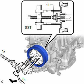
| (b) Using SST and the crankshaft pulley bolt, remove the crankshaft pulley assembly and crankshaft pulley bolt. SST: 09950-50013 09951-05010 09952-05010 09953-05020 09954-05070 09957-04010 HINT: Apply lubricant to the threads and end of SST. |
|
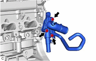
19. REMOVE WATER OUTLET
| (a) Using an 8 mm socket wrench, remove the 3 bolts, water outlet and water outlet gasket from the cylinder head sub-assembly. |
|
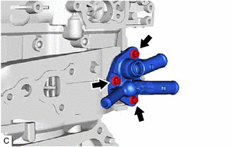
20. REMOVE OUTLET WATER BY-PASS SUB-ASSEMBLY
| (a) Using an 8 mm socket wrench, remove the 3 bolts, outlet water by-pass sub-assembly and outlet water pipe gasket from the cylinder head sub-assembly. |
|
21. REMOVE CYLINDER HEAD COVER SUB-ASSEMBLY
| (a) Using an 8 mm socket wrench, remove the 4 bolts (A). |
|
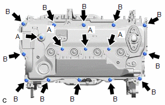
(b) Remove the 12 bolts (B) and cylinder head cover sub-assembly from the camshaft housing sub-assembly.
| (c) Remove the 7 cylinder head cover gaskets from the cylinder head cover sub-assembly. |
|
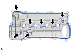
| (d) Remove the camshaft bearing cap oil hole gasket from the No. 1 camshaft bearing cap. |
|
22. REMOVE SPARK PLUG TUBE GASKET
| (a) Using a screwdriver, pry out the 4 spark plug tube gaskets from the cylinder head cover sub-assembly. NOTICE: Be careful not to damage the cylinder head cover sub-assembly. HINT: Tape the screwdriver tip before use. |
|
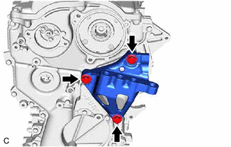
23. REMOVE ENGINE MOUNTING BRACKET RH
| (a) Remove the 3 bolts and engine mounting bracket RH from the No. 2 timing chain cover assembly. |
|
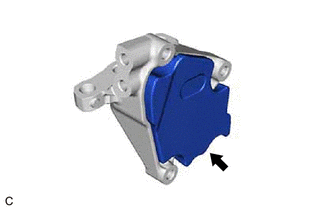
24. REMOVE ENGINE MOUNTING INSULATOR RH
| (a) Remove the engine mounting insulator RH from the engine mounting bracket RH. |
|
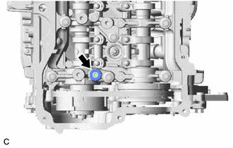
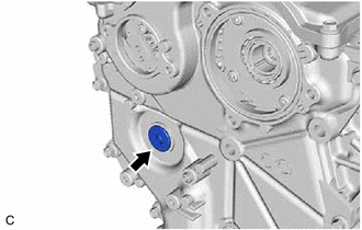
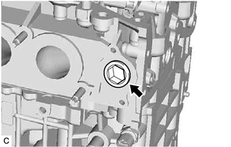
25. REMOVE STRAIGHT SCREW PLUG
| (a) Using a 10 mm hexagon wrench, remove the straight screw plug from the No. 2 timing chain cover assembly. |
|
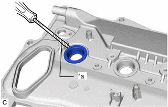
26. REMOVE NO. 2 TIMING CHAIN COVER ASSEMBLY
| (a) Remove the 20 bolts. |
|
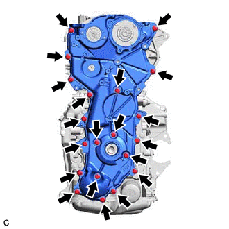
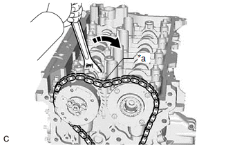
(b) Remove the No. 2 timing chain cover assembly from the timing chain cover assembly by prying the No. 2 timing chain cover assembly with a screwdriver with its tip wrapped with protective tape.
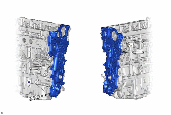
| *a | Protective Tape | - | - |
NOTICE:
Be careful not to damage the contact surfaces of the No. 2 timing chain cover assembly and timing chain cover assembly.
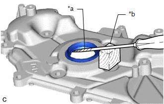
27. REMOVE TIMING CHAIN COVER OIL SEAL
| (a) Using a screwdriver and wooden block, pry out the timing chain cover oil seal. NOTICE: Do not damage the surface of the timing chain cover oil seal press fit hole. HINT: Tape the screwdriver tip before use. |
|
28. SET NO. 1 CYLINDER TO TDC (COMPRESSION)
(a) Temporarily install the crankshaft pulley bolt.
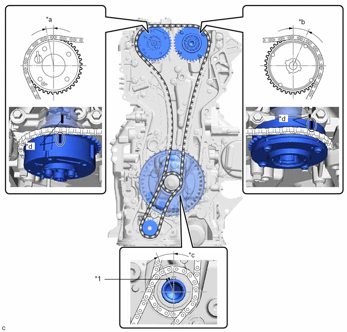
| *1 | Crankshaft Timing Gear Key | - | - |
| *a | Approximately 11.4° | *b | Approximately 23.7° |
| *c | Approximately 24.3° | *d | Timing Mark |
(b) Rotate the crankshaft clockwise and align the crankshaft timing gear key as shown in the illustration.
(c) Check that the timing marks on the camshaft timing exhaust gear assembly and camshaft timing gear assembly are as shown in the illustration.
(d) Remove the crankshaft pulley bolt.
HINT:
As the No. 2 camshaft may rotate counterclockwise strongly when the crankshaft pulley bolt is removed, use a wrench to hold the hexagonal portion of the No. 2 camshaft.
29. REMOVE OIL PUMP DRIVE CHAIN SUB-ASSEMBLY
(a) Temporarily install the crankshaft pulley assembly with the crankshaft pulley bolt.
| (b) Using SST, hold the crankshaft pulley assembly and remove the bolt. SST: 09213-54015 SST: 09330-00021 |
|
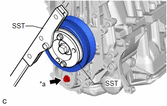
(c) Remove SST, the crankshaft pulley bolt and crankshaft pulley assembly.
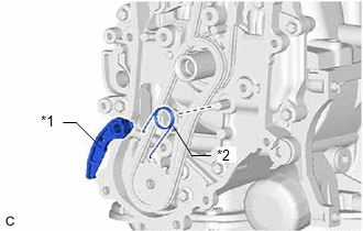
| (d) Remove the chain tensioner plate and chain damper spring. |
|
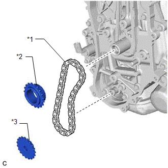
| (e) Remove the oil pump drive sprocket, oil pump drive shaft sprocket and oil pump drive chain sub-assembly. |
|
30. REMOVE CAMSHAFT TIMING GEAR ASSEMBLY
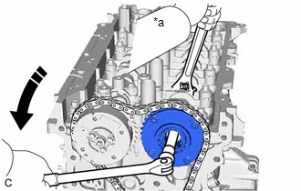
(a) Hold the hexagonal portion of the No. 2 camshaft with a wrench and turn the camshaft timing exhaust gear assembly clockwise to loosen the chain sub-assembly between the camshaft timing exhaust gear assembly and camshaft timing gear assembly.
| *a | Loosen |
.png) | Turn |
(b) Using a wrench, hold the hexagonal portion of the camshaft.
NOTICE:
- Be careful not to damage the camshaft housing sub-assembly, cylinder head sub-assembly and spark plug tube with the wrench.
- Do not disassemble the camshaft timing gear assembly.
| *a | Hold |
| | Turn |
(c) Using a 10 mm bi-hexagonal wrench, remove the bolt and camshaft timing gear assembly from the camshaft.
31. REMOVE CHAIN SUB-ASSEMBLY
| (a) Remove the crankshaft timing sprocket and chain sub-assembly. |
|
32. REMOVE NO. 1 CHAIN TENSIONER ASSEMBLY
| (a) Using an 8 mm socket wrench, remove the bolt. |
|
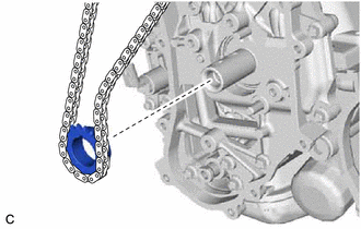
(b) Remove the nut and No. 1 chain tensioner assembly.
NOTICE:
Make sure that the plunger, check ball assembly and spring do not come out.
(c) Use tape to hold the plunger inside the No. 1 chain tensioner assembly.

| *a | Tape |
NOTICE:
- Make sure that the plunger, check ball assembly and spring do not come out.
-
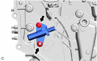
If the No. 1 chain tensioner assembly comes apart, reinstall the parts as shown in the illustration.
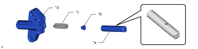
*a
Plunger
*b
Check Ball Assembly
*c
Spring
*d
No. 1 Chain Tensioner Assembly Body
33. REMOVE CHAIN TENSIONER SLIPPER
| (a) Remove the bolt and chain tensioner slipper. |
|
34. REMOVE NO. 1 CHAIN VIBRATION DAMPER
| (a) Remove the 2 bolts and No. 1 chain vibration damper. |
|
35. REMOVE CAMSHAFT TIMING EXHAUST GEAR ASSEMBLY
| (a) Using a wrench, hold the hexagonal portion of the No. 2 camshaft. NOTICE: Be careful not to damage the camshaft housing sub-assembly, cylinder head sub-assembly or spark plug tube with the wrench. |
|
(b) Using a 5 mm hexagon socket wrench, remove the 3 bolts.
| (c) Remove the camshaft timing exhaust gear assembly and camshaft timing valve assembly. |
|

36. REMOVE TIMING CHAIN COVER ASSEMBLY
| (a) Remove the 19 bolts from the camshaft housing sub-assembly, cylinder head sub-assembly, cylinder block sub-assembly, stiffening crankcase assembly and oil pump assembly. |
|
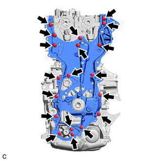
(b) Remove the timing chain cover assembly by prying between the cylinder head sub-assembly, camshaft housing sub-assembly, cylinder block sub-assembly, oil pump assembly and stiffening crankcase assembly with a screwdriver with its tip wrapped with protective tape.
| *a | Protective Tape | - | - |
NOTICE:
Be careful not to damage the contact surfaces of the cylinder head sub-assembly, camshaft housing sub-assembly, cylinder block sub-assembly, oil pump assembly, stiffening crankcase assembly and timing chain cover assembly.
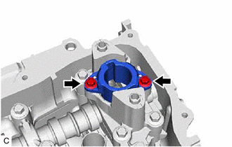
37. REMOVE OIL NOZZLE VALVE SUB-ASSEMBLY
| (a) Remove the oil nozzle valve sub-assembly from the cylinder block sub-assembly. |
|
38. REMOVE CRANKSHAFT TIMING GEAR KEY
| (a) Using a screwdriver, remove the 2 crankshaft timing gear keys. NOTICE: Be careful not to damage the crankshaft. HINT: Tape the screwdriver tip before use. |
|
39. REMOVE FUEL PUMP LIFTER GUIDE
| (a) Using an 8 mm socket wrench, remove the 2 bolts and fuel pump lifter guide from the No. 4 camshaft bearing cap. |
|
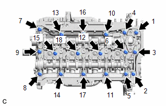
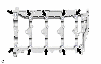
40. REMOVE CAMSHAFT HOUSING SUB-ASSEMBLY
| (a) Uniformly loosen and remove the 18 bolts in the order shown in the illustration. |
|
| (b) Remove the camshaft housing sub-assembly by prying between the cylinder head sub-assembly and camshaft housing sub-assembly with a screwdriver. NOTICE: Be careful not to damage the contact surfaces of the cylinder head sub-assembly and camshaft housing sub-assembly. HINT: Tape the screwdriver tip before use. |
|
41. REMOVE CAMSHAFT BEARING CAP
| (a) Remove the 8 bolts in the order shown in the illustration. |
|
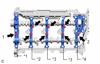
(b) Remove the No. 1 camshaft bearing cap, No. 2 camshaft bearing cap, 2 No. 3 camshaft bearing caps and No. 4 camshaft bearing cap.
HINT:
Arrange the removed parts in such a way that they can be reinstalled to their original locations.
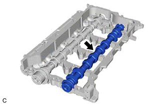
42. REMOVE CAMSHAFT
| (a) Remove the camshaft from the camshaft housing sub-assembly. |
|
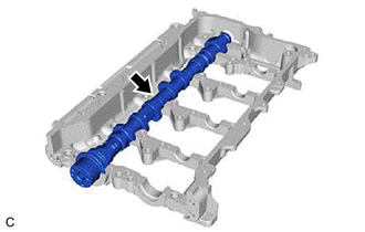
43. REMOVE NO. 2 CAMSHAFT
| (a) Remove the No. 2 camshaft from the camshaft housing sub-assembly. |
|
44. REMOVE CAMSHAFT BEARING CAP SETTING RING PIN
NOTICE:
It is not necessary to remove the camshaft bearing cap setting ring pins unless they are being replaced.
| (a) Remove the 10 camshaft bearing cap setting ring pins from the camshaft housing sub-assembly. |
|
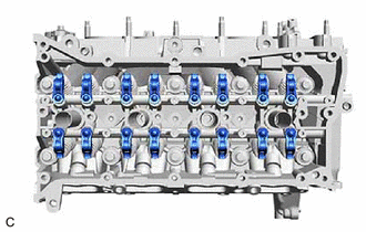
45. REMOVE NO. 1 VALVE ROCKER ARM SUB-ASSEMBLY
| (a) Remove the 16 No. 1 valve rocker arm sub-assemblies. HINT: Arrange the removed parts in such a way that they can be reinstalled to their original locations. |
|
46. REMOVE VALVE LASH ADJUSTER ASSEMBLY
| (a) Remove the 16 valve lash adjuster assemblies from the cylinder head sub-assembly. HINT: Arrange the removed parts in such a way that they can be reinstalled to their original locations. |
|
47. REMOVE VALVE STEM CAP
| (a) Remove the 16 valve stem caps from the cylinder head sub-assembly. HINT: Arrange the removed parts in such a way that they can be reinstalled to their original locations. |
|
48. REMOVE NO. 3 STRAIGHT SCREW PLUG
| (a) Using a 14 mm straight hexagon wrench, remove the No. 3 straight screw plug from the cylinder head sub-assembly. |
|
49. REMOVE CYLINDER HEAD SUB-ASSEMBLY
(a) Using a 12 mm socket wrench, uniformly loosen the 10 cylinder head set bolts in the order shown in the illustration. Remove the 10 cylinder head set bolts and 10 plate washers.
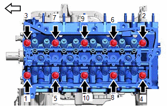
.png) | Front of Engine |
NOTICE:
- Be careful not to drop the plate washers into the cylinder head sub-assembly.
- Warpage or cracking of the cylinder head sub-assembly may result from removing the cylinder head set bolts in the incorrect order.
HINT:
Arrange the removed parts in such a way that they can be reinstalled to their original locations.
(b) Remove the cylinder head sub-assembly from the cylinder block sub-assembly.
50. REMOVE CYLINDER HEAD GASKET
Click here
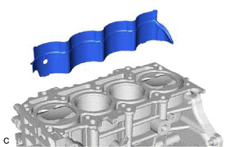
51. REMOVE CYLINDER BLOCK WATER JACKET SPACER
| (a) Remove the cylinder block water jacket spacer from the exhaust side of the cylinder block sub-assembly. NOTICE: Be sure to remove the cylinder block water jacket spacer. If it is not removed, it may fall and become damaged when the cylinder block sub-assembly is inverted. |
|
52. REMOVE OIL FILTER SUB-ASSEMBLY
Click here
53. REMOVE OIL FILTER UNION
(a) Using a 12 mm hexagon socket wrench, remove the oil filter union from the stiffening crankcase assembly.
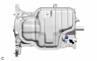
54. REMOVE OIL PAN DRAIN PLUG
(a) Remove the oil pan drain plug and gasket from the No. 2 oil pan sub-assembly.
55. REMOVE NO. 2 OIL PAN SUB-ASSEMBLY
| (a) Remove the 11 bolts and 2 nuts. |
|
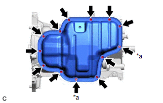
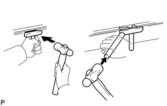
| (b) Insert the blade of an oil pan seal cutter between the No. 2 oil pan sub-assembly and stiffening crankcase assembly, cut through the applied sealer and remove the No. 2 oil pan sub-assembly. NOTICE:
|
|
56. REMOVE OIL STRAINER SUB-ASSEMBLY
| (a) Using an 8 mm socket wrench, remove the bolt, oil strainer sub-assembly and oil strainer gasket. |
|
57. REMOVE ENGINE OIL LEVEL SENSOR
Click here
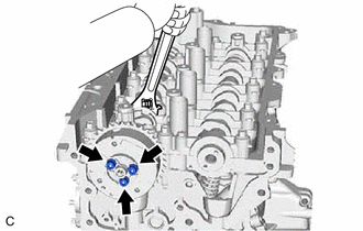
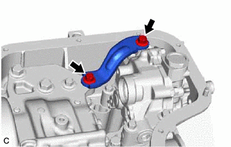
58. REMOVE OIL PUMP BRACKET
| (a) Remove the 2 bolts and oil pump bracket. |
|
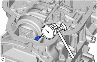
59. INSPECT CRANKSHAFT BACKLASH
| (a) Using a dial indicator, measure the backlash of the crankshaft and balance shaft as shown in the illustration. Standard Backlash: 0.05 to 0.20 mm (0.00197 to 0.00787 in.) Maximum Backlash: 0.20 mm (0.00787 in.) If the backlash is more than the maximum, replace the engine balancer assembly. |
|
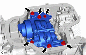
60. REMOVE ENGINE BALANCER ASSEMBLY
| (a) Remove the 6 bolts and engine balancer assembly from the stiffening crankcase assembly. NOTICE: Do not disassemble the engine balancer assembly. |
|
61. REMOVE OIL PUMP ASSEMBLY
Click here
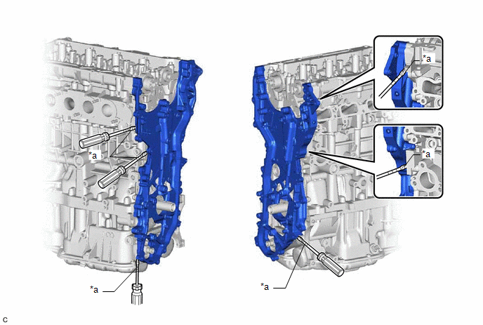
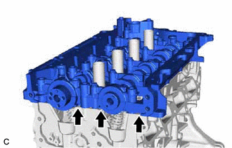
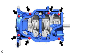
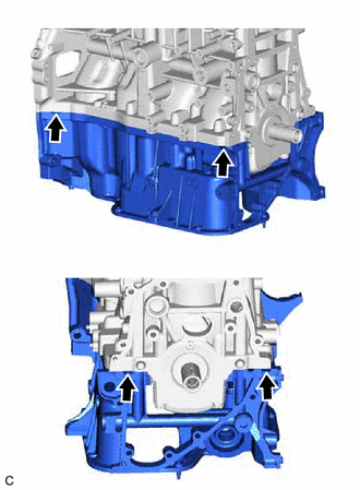
62. REMOVE STIFFENING CRANKCASE ASSEMBLY
| (a) Remove the 7 bolts. |
|
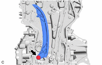
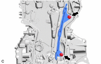
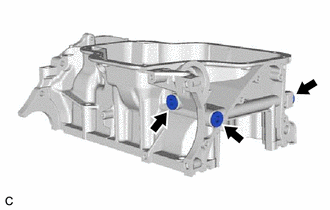
| (b) Using a screwdriver, remove the stiffening crankcase assembly by prying between the stiffening crankcase assembly and cylinder block sub-assembly at the places shown in the illustration. NOTICE: Be careful not to damage the contact surfaces of the cylinder block sub-assembly and stiffening crankcase assembly. HINT: Tape the screwdriver tip before use. |
|
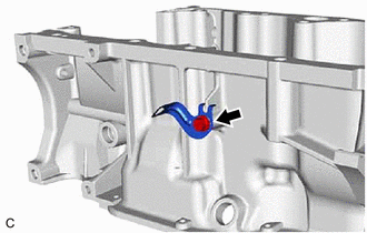
63. REMOVE STRAIGHT SCREW PLUG
| (a) Using a 10 mm hexagon socket wrench, remove the 3 straight screw plugs and 3 gaskets from the stiffening crankcase assembly. |
|
64. REMOVE WIRE HARNESS CLAMP BRACKET
| (a) Using an 8 mm socket wrench, remove the bolt and wire harness clamp bracket from the stiffening crankcase assembly. |
|
65. REMOVE STUD BOLT
NOTICE:
If a stud bolt is deformed or its threads are damaged, replace it.
66. REMOVE RING PIN
NOTICE:
It is not necessary to remove the ring pins unless they are being replaced.
67. REMOVE STRAIGHT PIN
NOTICE:
It is not necessary to remove the straight pins unless they are being replaced.
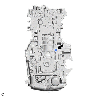
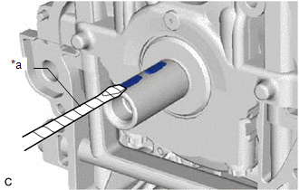
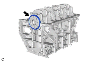
68. REMOVE REAR ENGINE OIL SEAL
| (a) Remove the rear engine oil seal from the cylinder block sub-assembly. |
|
READ NEXT:
 Inspection
INSPECTION PROCEDURE 1. INSPECT NO. 1 VALVE ROCKER ARM SUB-ASSEMBLY (a) Turn the roller by hand to check that it turns smoothly. HINT: If the roller does not turn smoothly, replace the No. 1 valve
Front Crankshaft Oil Seal
ComponentsCOMPONENTS ILLUSTRATION *1 CRANKSHAFT PULLEY ASSEMBLY *2 TIMING CHAIN COVER OIL SEAL *3 CRANKSHAFT PULLEY BOLT *4 V-RIBBED BELT N*m (kgf*cm, ft.*lbf): Specified t
Rear Crankshaft Oil Seal
ComponentsCOMPONENTS ILLUSTRATION *1 DRIVE PLATE AND RING GEAR SUB-ASSEMBLY *2 REAR ENGINE OIL SEAL *3 NO. 1 CRANKSHAFT POSITION SENSOR PLATE *4 REAR DRIVE PLATE SPACER N*m
SEE MORE:
Lost Communication with Hybrid Powertrain Control Module (Hybrid/EV Battery Local Bus) Missing Message (U115087)
DESCRIPTION The battery ECU assembly transmits and receives signals via CAN communication to and from the hybrid vehicle control ECU. DTC No. Detection Item DTC Detection Condition Trouble Area MIL Warning Indicate U115087 Lost Communication with Hybrid Powertrain Control Module (
Certification ECU Vehicle Information Reading/Writing Process Malfunction (B15F7)
DESCRIPTION This DTC is stored when items controlled by the certification ECU (smart key ECU assembly) cannot be customized via the audio and visual system vehicle customization screen. HINT: The certification ECU (smart key ECU assembly) controls the smart access system with push-button start (for
