Lexus ES: Lost Communication with Hybrid Powertrain Control Module (Hybrid/EV Battery Local Bus) Missing Message (U115087)
DESCRIPTION
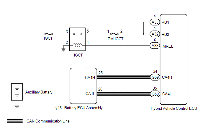
The battery ECU assembly transmits and receives signals via CAN communication to and from the hybrid vehicle control ECU.
| DTC No. | Detection Item | DTC Detection Condition | Trouble Area | MIL | Warning Indicate |
|---|---|---|---|---|---|
| U115087 | Lost Communication with Hybrid Powertrain Control Module (Hybrid/EV Battery Local Bus) Missing Message | The battery ECU assembly does not receive any signals from the hybrid vehicle control ECU for 1 second or more. (1 trip detection logic) |
| Comes on | Master Warning Light: Comes on |
MONITOR DESCRIPTION
If the battery ECU assembly cannot communicate with the hybrid vehicle control ECU via CAN communication, it will illuminate the MIL and store a DTC.
MONITOR STRATEGY
| Related DTCs | U1150 (INF U115087): Lost communication with hybrid control module (battery bus) |
| Required sensors/components | Battery ECU assembly |
| Frequency of operation | Continuous |
| Duration | TMC's intellectual property |
| MIL operation | Immediately |
| Sequence of operation | None |
TYPICAL ENABLING CONDITIONS
| The monitor will run whenever the following DTCs are not stored | TMC's intellectual property |
| Other conditions belong to TMC's intellectual property | - |
TYPICAL MALFUNCTION THRESHOLDS
| TMC's intellectual property | - |
COMPONENT OPERATING RANGE
| Battery ECU assembly | DTC U1150 (INF U115087) is not detected |
CONFIRMATION DRIVING PATTERN
HINT:
-
After repair has been completed, clear the DTC and then check that the vehicle has returned to normal by performing the following All Readiness check procedure.
Click here
.gif)
-
When clearing the permanent DTCs, refer to the "CLEAR PERMANENT DTC" procedure.
Click here
- Connect the Techstream to the DLC3.
- Turn the power switch on (IG) and turn the Techstream on.
- Clear the DTCs (even if no DTCs are stored, perform the clear DTC procedure).
- Turn the power switch off and wait for 2 minutes or more.
- Turn the power switch on (IG) and turn the Techstream on.
-
With power switch on (IG) and wait for 2 minutes or more.[*1]
HINT:
[*1]: Normal judgment procedure.
The normal judgment procedure is used to complete DTC judgment and also used when clearing permanent DTCs.
- Enter the following menus: Powertrain / HV Battery / Utility / All Readiness.
-
Check the DTC judgment result.
HINT:
- If the judgment result shows NORMAL, the system is normal.
- If the judgment result shows ABNORMAL, the system has a malfunction.
- If the judgment result shows INCOMPLETE or N/A, perform the normal judgment procedure again.
WIRING DIAGRAM
CAUTION / NOTICE / HINT
CAUTION:
-
Before the following operations are conducted, take precautions to prevent electric shock by turning the power switch off, wearing insulated gloves, and removing the service plug grip from HV battery.
.png)
- Inspecting the high-voltage system
- Disconnecting the low voltage connector of the inverter with converter assembly
- Disconnecting the low voltage connector of the HV battery
-
To prevent electric shock, make sure to remove the service plug grip to cut off the high voltage circuit before servicing the vehicle.

-
After removing the service plug grip from the HV battery, put it in your pocket to prevent other technicians from accidentally reconnecting it while you are working on the high-voltage system.

-
After removing the service plug grip, wait for at least 10 minutes before touching any of the high-voltage connectors or terminals. After waiting for 10 minutes, check the voltage at the terminals in the inspection point in the inverter with converter assembly. The voltage should be 0 V before beginning work.
Click here
HINT:
Waiting for at least 10 minutes is required to discharge the high-voltage capacitor inside the inverter with converter assembly.

*a
Without waiting for 10 minutes
NOTICE:
After turning the power switch off, waiting time may be required before disconnecting the cable from the negative (-) auxiliary battery terminal. Therefore, make sure to read the disconnecting the cable from the negative (-) auxiliary battery terminal notices before proceeding with work.
Click here
PROCEDURE
| 1. | CHECK DTC OUTPUT (HYBRID CONTROL) |
(a) Connect the Techstream to the DLC3.
(b) Turn the power switch on (IG).
(c) Enter the following menus: Powertrain / Hybrid Control / Trouble Codes.
(d) Check and record any Hybrid Control DTCs and freeze frame data. Check for DTCs.
Powertrain > Hybrid Control > Trouble Codes| Result | Proceed to |
|---|---|
| DTCs related to Hybrid Control System are not output. | A |
| DTCs related to Hybrid Control System are output. | B |
(e) Turn the power switch off.
| B | .gif) | GO TO DTC CHART (HYBRID CONTROL SYSTEM) |
|
.gif)
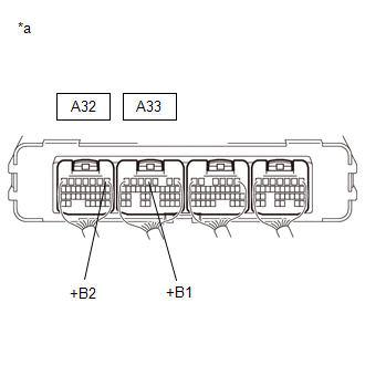
| 2. | CHECK HYBRID VEHICLE CONTROL ECU (VOLTAGE) |
(a) Turn the power switch on (IG).
| (b) Measure the voltage according to the value(s) in the table below. Standard Voltage:
|
|
(c) Turn the power switch off.
| NG | | REPAIR OR REPLACE HARNESS OR CONNECTOR (BATTERY ECU ASSEMBLY POWER SOURCE CIRCUIT) |
|
| 3. | CHECK HYBRID VEHICLE CONTROL ECU |
CAUTION:
Be sure to wear insulated gloves and protective goggles.
(a) Check that the service plug grip is not installed.
NOTICE:
After removing the service plug grip, do not turn the power switch on (READY), unless instructed by the repair manual because this may cause a malfunction.
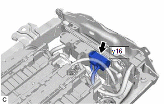
(b) Remove the No. 1 HV battery hose.
Click here
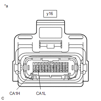
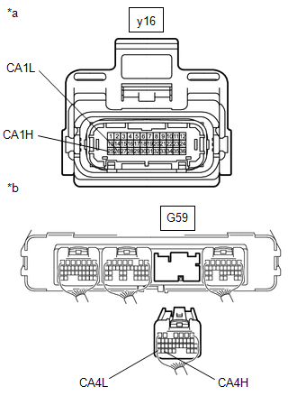
| (c) Disconnect the y16 battery ECU assembly connector. NOTICE: Before disconnecting the connector, check that it is not loose or disconnected. |
|
| (d) Measure the resistance according to the value(s) in the table below. Standard Resistance:
|
|
(e) Reconnect the y16 battery ECU assembly connector.
(f) Install the No. 1 HV battery hose.
| OK | | REPLACE BATTERY ECU ASSEMBLY |
|
| 4. | CHECK HARNESS AND CONNECTOR (HYBRID VEHICLE CONTROL ECU - BATTERY ECU ASSEMBLY) |
CAUTION:
Be sure to wear insulated gloves and protective goggles.
(a) Check that the service plug grip is not installed.
NOTICE:
After removing the service plug grip, do not turn the power switch on (READY), unless instructed by the repair manual because this may cause a malfunction.
(b) Disconnect the G59 hybrid vehicle control ECU connector.
NOTICE:
Before disconnecting the connector, check that it is not loose or disconnected.
(c) Remove the No. 1 HV battery hose.
Click here
| (d) Disconnect the y16 battery ECU assembly connector. NOTICE:
|
|
| (e) Measure the resistance according to the value(s) in the table below. Standard Resistance:
|
|
(f) Reconnect the y16 battery ECU assembly connector.
(g) Install the No. 1 HV battery hose.
(h) Reconnect the G59 hybrid vehicle control ECU connector.
| OK | | REPLACE HYBRID VEHICLE CONTROL ECU |
| NG | | REPAIR OR REPLACE HARNESS OR CONNECTOR |
READ NEXT:
 "HAVE TRACTION BATTERY INSPECTED" is displayed
DESCRIPTION The battery ECU assembly monitors the SOC (state of charge) of the HV battery. When it finds the HV battery has deteriorated excessively, it will display "Have Traction Battery Inspected"
ECU Power Source Circuit
DESCRIPTION If the power switch is on (IG), the battery ECU assembly applies current to the MREL terminal to turn the IGCT relay on. This supplies power to the IGCT terminals. WIRING DIAGRAM CAUTION
SEE MORE:
Front Passenger Side Power Mirror cannot be Adjusted with Power Mirror Switch
DESCRIPTION The outer mirror switch assembly sends the mirror adjust switch signals to the main body ECU (multiplex network body ECU). The main body ECU (multiplex network body ECU) then sends the received mirror adjust switch signals to the outer mirror control ECU assembly (front passenger door) v
Installation
INSTALLATION PROCEDURE 1. INSTALL ENGINE OIL PRESSURE SWITCH ASSEMBLY (a) Apply adhesive to 2 or 3 threads of the engine oil pressure switch assembly. Adhesive: Toyota Genuine Adhesive 1344, Three Bond 1344 or equivalent NOTICE:
Do not apply adhesive to the oil inlet port of the engine oil
