Lexus ES: Disassembly
DISASSEMBLY
CAUTION / NOTICE / HINT
NOTICE:
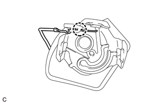
Do not disconnect the tube shown in the illustration when disassembling the fuel suction tube with pump and gauge assembly. Doing so will cause reassembly of the fuel suction tube with pump and gauge assembly to be impossible as the tube is pressed into the fuel suction plate sub-assembly.
.png)
| *a | Tube |
PROCEDURE
1. REMOVE FUEL SENDER GAUGE ASSEMBLY
Click here .gif)
2. REMOVE FUEL PUMP WITH FILTER ASSEMBLY
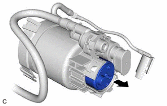
(a) Remove the harness protector from the fuel pump harness.
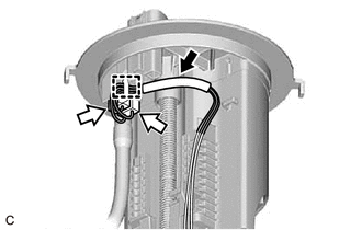
.png) | Harness Protector |
.png) | Fuel Pump Harness Connector |
(b) Disconnect the 2 fuel pump harness connectors.
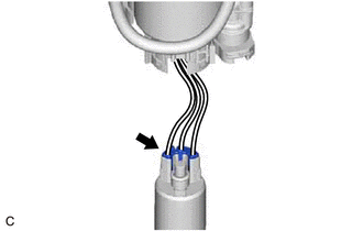
(c) Disengage the clamp to disconnect the fuel pump harness from the fuel suction plate sub-assembly.
NOTICE:
Do not damage the wire harness.
| (d) Using a screwdriver with its tip wrapped with protective tape, disengage the claw. NOTICE: Do not damage the fuel sub-tank. |
|
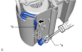
(e) Disengage the clamp and disconnect the fuel pump filter hose from the fuel sub-tank.
NOTICE:
Do not damage the fuel sub-tank.
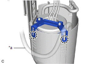
| (f) Disengage the 2 claws and remove the fuel filter from the fuel sub-tank. NOTICE: Do not do anything which may separate the tube from either the fuel suction plate sub-assembly or fuel filter, such as applying excessive force to the tube. Click here |
|
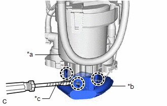
| (g) Using a screwdriver with its tip wrapped with protective tape, disengage the 3 claws, and remove the suction filter from the fuel filter. NOTICE: Do not damage the fuel filter or suction filter. |
|
| (h) Disengage the claw to disconnect the fuel pump harness from the suction filter. |
|
| (i) Remove the fuel pump from the fuel filter. |
|
| (j) Disconnect the fuel pump harness connector to remove the fuel pump harness from the fuel pump. |
|
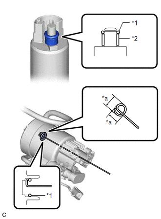
| (k) Remove the O-ring and fuel pump spacer from the fuel pump. NOTICE: Be careful not to damage the sealing surface. HINT: If the O-ring still remains in the fuel filter, remove it using a wire tip (1 mm (0.0394 in.) diameter) that is formed as shown in the illustration. |
|
READ NEXT:
 Inspection
INSPECTION PROCEDURE 1. INSPECT FUEL PUMP WITH FILTER ASSEMBLY (a) Measure the resistance according to the value(s) in the table below. Standard Resistance: Tester Connection Specified Condit
Reassembly
REASSEMBLY PROCEDURE 1. INSTALL FUEL PUMP WITH FILTER ASSEMBLY HINT: Perform "Inspection After Repair" after replacing the fuel pump with filter assembly. Click here (a) Apply gasoline to a new
Installation
INSTALLATION PROCEDURE 1. INSTALL FUEL SUCTION TUBE WITH PUMP AND GAUGE ASSEMBLY (a) Install a new fuel suction tube set gasket to the fuel tank assembly. (b) Set the fuel suction tube with pump and g
SEE MORE:
Installation
INSTALLATION PROCEDURE 1. INSTALL ACTIVE NOISE CONTROL MICROPHONE (for Front Side) HINT:
Use the same procedure for the RH side and LH side.
The following procedure is for the LH side.
(a) Connect the connector. Install in this Direction (b) Engage the 2 claws to install the active
Hybrid/EV Battery Positive Contactor Circuit Short to Auxiliary Battery or Open (P0AD915)
DESCRIPTION Refer to the description for DTC P0AE411. Click here DTC No. Detection Item DTC Detection Condition Trouble Area MIL Warning Indicate P0AD915 Hybrid/EV Battery Positive Contactor Circuit Short to Auxiliary Battery or Open Open or short to +B in the SMRB circuit: Pr
