Lexus ES: Differential Oil Seal (for Lh Side)
Components
COMPONENTS
ILLUSTRATION
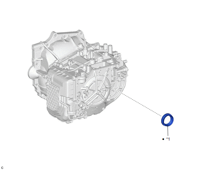
| *1 | FRONT DRIVE SHAFT OIL SEAL LH | - | - |
| ● | Non-reusable part | - | - |
Replacement
REPLACEMENT
CAUTION / NOTICE / HINT
The necessary procedures (adjustment, calibration, initialization or registration) that must be performed after parts are removed and installed, or replaced during front drive shaft oil seal LH removal/installation are shown below.
Necessary Procedures After Parts Removed/Installed/Replaced| Replaced Part or Performed Procedure | Necessary Procedure | Effect/Inoperative Function when Necessary Procedure not Performed | Link |
|---|---|---|---|
| Replacement of automatic transaxle fluid | ATF thermal degradation estimate reset | The value of the Data List item "ATF Thermal Degradation Estimate" is not estimated correctly | |
| Front wheel alignment adjustment |
|
| |
PROCEDURE
1. REMOVE FRONT DRIVE SHAFT ASSEMBLY LH
Click here .gif)
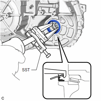
2. REMOVE FRONT DRIVE SHAFT OIL SEAL LH
| (a) Using SST, remove the front drive shaft oil seal LH from the automatic transaxle case sub-assembly. SST: 09308-00010 NOTICE: Be careful not to damage the automatic transaxle case sub-assembly. |
|
3. INSTALL FRONT DRIVE SHAFT OIL SEAL LH
(a) Using SST and a hammer, install a new front drive shaft oil seal LH to the automatic transaxle case sub-assembly.
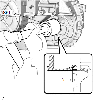
| *a | Depth |
SST: 09649-17010
SST: 09950-70010
09951-07100
Standard Depth:
-0.5 to 0.5 mm (-0.0197 to 0.0197 in.)
NOTICE:
-
Make sure that the outer lip of the front drive shaft oil seal LH is not pinched by SST.
.png)
*a
Correct
*b
Incorrect
*c
Outer Lip
- Do not allow foreign matter to attach to the inner lip and outer lip of the front drive shaft oil seal LH.
- Do not install the front drive shaft oil seal LH at an angle.
- Do not remove the grease from the inner lip and outer lip of the front drive shaft oil seal LH.
4. INSTALL FRONT DRIVE SHAFT ASSEMBLY LH
Click here
READ NEXT:
 Differential Oil Seal (for Rh Side)
ComponentsCOMPONENTS ILLUSTRATION *1 DRIVE SHAFT BEARING BRACKET *2 DIFFERENTIAL SIDE OIL SEAL *3 FRONT DRIVE SHAFT OIL SEAL RH - - Tightening torque for "Major areas invol
Components
COMPONENTS ILLUSTRATION *1 NO. 1 ENGINE UNDER COVER *2 NO. 2 ENGINE UNDER COVER ASSEMBLY *3 FRONT WHEEL OPENING EXTENSION PAD LH *4 FRONT WHEEL OPENING EXTENSION PAD RH *5 FR
SEE MORE:
Components
COMPONENTS ILLUSTRATION *1 NO. 1 OIL COOLER OUTLET TUBE SUB-ASSEMBLY *2 NO. 1 TRANSMISSION OIL FILLER TUBE *3 OIL COOLER UNION SUB-ASSEMBLY *4 OVERFLOW PLUG *5 PARK/NEUTRAL POSITION SWITCH ASSEMBLY *6 REFILL PLUG *7 TRANSMISSION CONTROL SHAFT LEVER *8 GASKET
How To Proceed With Troubleshooting
CAUTION / NOTICE / HINT HINT:
Use the following procedure to troubleshoot the power mirror control system (w/o Memory).
*: Use the Techstream.
PROCEDURE 1. VEHICLE BROUGHT TO WORKSHOP
NEXT 2. CUSTOMER PROBLEM ANALYSIS HINT:
In troubleshooting, confirm th
