Lexus ES: Differential Oil
Components
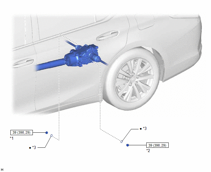
COMPONENTS
ILLUSTRATION
|
*1 |
REAR DIFFERENTIAL FILLER PLUG |
*2 |
REAR DIFFERENTIAL DRAIN PLUG |
|
*3 |
GASKET |
- |
- |
.png) |
N*m (kgf*cm, ft.*lbf): Specified torque |
● |
Non-reusable part |
Replacement
REPLACEMENT
PROCEDURE
1. DRAIN DIFFERENTIAL OIL
(a) Stop the vehicle on a level surface.
|
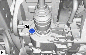
(b) Using a 10 mm socket hexagon wrench, remove the rear differential filler plug and gasket. |
|
|
(c) Using a 10 mm socket hexagon wrench, remove the rear differential drain plug and gasket. |
|
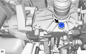
(d) Drain the differential oil.
(e) Install a new gasket and the rear differential drain plug.
Torque:
39 N·m {398 kgf·cm, 29 ft·lbf}
2. ADD DIFFERENTIAL OIL
|
(a) Add Toyota Genuine Differential gear oil LT SAE 75W-85 API GL-5 or equivalent. |
|
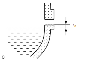
(b) Pour oil into the rear differential carrier assembly so that the oil level is within 0 to 5 mm (0 to 0.196 in.) of the bottom of the filler plug opening.
NOTICE:
Excessively large or small quantities of oil may cause problems.
Recommended viscosity:
SAE 75W-85
Standard oil grade:
Toyota genuine differential gear oil LT API GL-5 or equivalent
Standard differential oil capacity:
0.45 to 0.55 liters (0.48 to 0.58 US qts., 0.40 to 0.48 Imp. qts.)
|
(c) Wait approximately 5 minutes and check that the oil level has not changed. |
|
(d) Using a 10 mm socket hexagon wrench, install a new gasket and the rear differential filler plug.
Torque:
39 N·m {398 kgf·cm, 29 ft·lbf}
(e) Drive the vehicle and check the oil level again. If necessary, add differential oil.
READ NEXT:
 Components
COMPONENTS
ILLUSTRATION
*1
FRONT FLEXIBLE HOSE
*2
GASKET
*3
BRAKE LINE
*4
FRONT SPEED SENSOR
Removal
REMOVAL
CAUTION / NOTICE / HINT
The necessary procedures (adjustment, calibration, initialization, or registration)
that must be performed after parts are removed and installed, or replaced during
SEE MORE:
Operation Check
OPERATION CHECK DCM OPERATION HISTORY HINT:
This function shows the telematics network status when the DCM (telematics transceiver) was operated. Use this when no DTC is present but this telematics system was unable to connect to the call center. This symptom may occur if cell phone signal streng
System Voltage Circuit Short to Ground or Open (P056014)
DESCRIPTION The battery supplies electricity to the ECM even when the engine switch is off. This power allows the ECM to store data such as DTC history and freeze frame data. If the battery voltage falls below a minimum level, the stored ECM data will be cleared and the ECM will determine that there
