
Lexus ES: Components
COMPONENTS
ILLUSTRATION
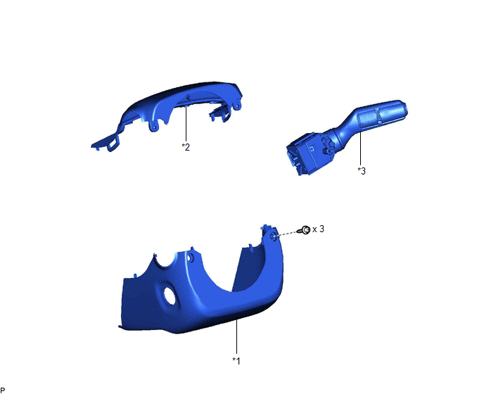
| *1 | LOWER STEERING COLUMN COVER SUB-ASSEMBLY | *2 | UPPER STEERING COLUMN COVER |
| *3 | WINDSHIELD WIPER SWITCH ASSEMBLY | - | - |
READ NEXT:
 Removal
REMOVAL PROCEDURE 1. CHANGE POWER TILT AND POWER TELESCOPIC STEERING COLUMN SYSTEM SETTINGS (for Power Tilt and Power Telescopic Steering Column) Click here 2. REMOVE LOWER STEERING COLUMN COVER S
Inspection
INSPECTION PROCEDURE 1. INSPECT WINDSHIELD WIPER SWITCH ASSEMBLY (w/ Auto Wiper System) (a) Measure the resistance according to the value(s) in the table below. *A for Type A *B for Type B
Installation
INSTALLATION PROCEDURE 1. INSTALL WINDSHIELD WIPER SWITCH ASSEMBLY (a) Engage the claw to install the windshield wiper switch assembly as shown in the illustration. Install in this Direction
SEE MORE:
Precaution
PRECAUTION NOTICE:
This vehicle is equipped with an SRS (Supplemental Restraint System). Failure to carry out service operations in the correct sequence could cause the SRS to unexpectedly deploy during servicing. This may cause a serious accident. Before servicing (including inspection, replacem
Inspection
INSPECTION PROCEDURE 1. INSPECT FRONT DRIVE SHAFT ASSEMBLY (a) Check that there is no excessive play in the radial direction of the outboard joint. (b) Check that the inboard joint slides smoothly in the thrust direction. (c) Check that there is no excessive play in the radial directi
© 2016-2026 Copyright www.lexguide.net
