Lexus ES: Inspection
INSPECTION
PROCEDURE
1. INSPECT WINDSHIELD WIPER SWITCH ASSEMBLY (w/ Auto Wiper System)
(a) Measure the resistance according to the value(s) in the table below.
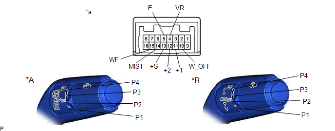
| *A | for Type A | *B | for Type B |
| *a | Component without harness connected (Windshield Wiper Switch Assembly) | - | - |
HINT:
If the result is not as specified, replace the windshield wiper switch assembly.
Standard Resistance:
Front Wiper Switch| Tester Connection | Switch Condition | Specified Condition |
|---|---|---|
| 14 (MIST) - 5 (E) | MIST | Below 1 Ω |
| 10 (W_OFF) - 5 (E) | OFF | |
| 13 (+S) - 5 (E) | AUTO | |
| 11 (+1) - 5 (E) | LO | |
| 12 (+2) - 5 (E) | HI |
| Tester Connection | Switch Condition | Specified Condition |
|---|---|---|
| 15 (WF) - 5 (E) | ON | Below 1 Ω |
| OFF | 10 kΩ or higher |
| Tester Connection | Switch Condition | Specified Condition |
|---|---|---|
| 4 (VR) - 5 (E) | P1 | 1102 to 1218 Ω |
| P2 | 570 to 630 Ω | |
| P3 | 256.5 to 283.5 Ω | |
| P4 | Below 1 Ω |
2. INSPECT WINDSHIELD WIPER SWITCH ASSEMBLY (w/o Auto Wiper System)
(a) Measure the resistance according to the value(s) in the table below.
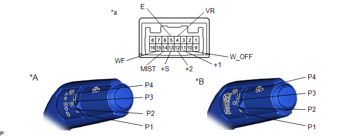
| *A | for Type A | *B | for Type B |
| *a | Component without harness connected (Windshield Wiper Switch Assembly) | - | - |
Standard Resistance:
Front Wiper Switch| Tester Connection | Condition | Specified Condition |
|---|---|---|
| 14 (MIST) - 5 (E) | MIST position | Below 1 Ω |
| Except MIST position | 10 kΩ or higher | |
| 10 (W_OFF) - 5 (E) | OFF position | Below 1 Ω |
| Except OFF position | 10 kΩ or higher | |
| 13 (+S) - 5 (E) | INT position | Below 1 Ω |
| Except INT position | 10 kΩ or higher | |
| 11 (+1) - 5 (E) | LO position | Below 1 Ω |
| Except LO position | 10 kΩ or higher | |
| 12 (+2) - 5 (E) | HI position | Below 1 Ω |
| Except HI position | 10 kΩ or higher |
| Tester Connection | Condition | Specified Condition |
|---|---|---|
| 15 (WF) - 5 (E) | ON position | Below 1 Ω |
| OFF position | 10 kΩ or higher |
| Tester Connection | Condition | Specified Condition |
|---|---|---|
| 4 (VR) - 5 (E) | P1 position | 1102 Ω to 1218 Ω |
| P2 position | 570 Ω to 630 Ω | |
| P3 position | 256.5 Ω to 283.5 Ω | |
| P4 position | Below 1 Ω |
HINT:
If the result is not as specified, replace the windshield wiper switch assembly.
READ NEXT:
 Installation
INSTALLATION PROCEDURE 1. INSTALL WINDSHIELD WIPER SWITCH ASSEMBLY (a) Engage the claw to install the windshield wiper switch assembly as shown in the illustration. Install in this Direction
SEE MORE:
Dtc Check / Clear
DTC CHECK / CLEAR CHECK FOR DTC (a) Turn the engine switch off. (b) Connect the Techstream to the DLC3. (c) Turn the engine switch on (IG). (d) Turn the Techstream on. (e) Enter the following menus: Chassis / Air suspension / Trouble Codes. Chassis > Air suspension > Trouble Codes HINT: When f
Reassembly
REASSEMBLY CAUTION / NOTICE / HINT HINT:
Use the same procedure for the RH side and LH side.
The following procedure is for the LH side.
PROCEDURE 1. INSTALL HEADLIGHT SEAL (for TMC Made) HINT: Perform this procedure only when replacement of the headlight seal is necessary. (a) Clean the ins
