Lexus ES: Components
COMPONENTS
ILLUSTRATION
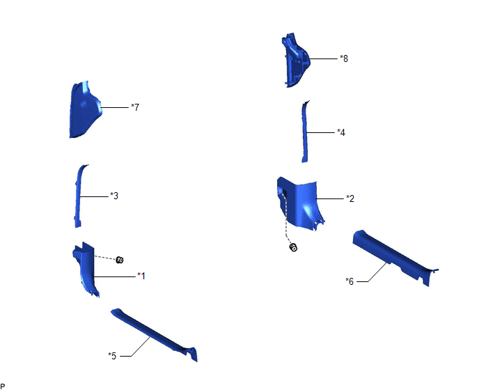
| *1 | COWL SIDE TRIM BOARD LH | *2 | COWL SIDE TRIM BOARD RH |
| *3 | FRONT DOOR OPENING TRIM COVER LH | *4 | FRONT DOOR OPENING TRIM COVER RH |
| *5 | FRONT DOOR SCUFF PLATE LH | *6 | FRONT DOOR SCUFF PLATE RH |
| *7 | INSTRUMENT SIDE PANEL LH | *8 | INSTRUMENT SIDE PANEL RH |
ILLUSTRATION
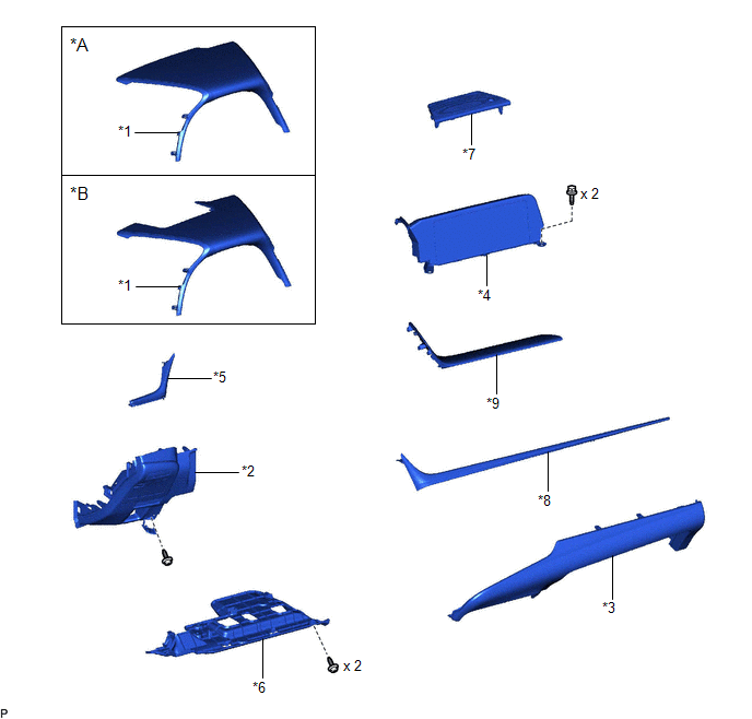
| *A | w/o Headup Display | *B | w/ Headup Display |
| *1 | INSTRUMENT CLUSTER FINISH PANEL SUB-ASSEMBLY | *2 | LOWER INSTRUMENT PANEL FINISH PANEL SUB-ASSEMBLY |
| *3 | LOWER INSTRUMENT PANEL SUB-ASSEMBLY | *4 | MULTI-DISPLAY ASSEMBLY WITH CLOCK |
| *5 | NO. 1 INSTRUMENT CLUSTER MOULDING | *6 | NO. 1 INSTRUMENT PANEL UNDER COVER SUB-ASSEMBLY |
| *7 | NO. 1 SPEAKER OPENING COVER ASSEMBLY | *8 | NO. 2 INSTRUMENT CLUSTER MOULDING |
| *9 | UPPER INSTRUMENT PANEL FINISH PANEL SUB-ASSEMBLY | - | - |
ILLUSTRATION
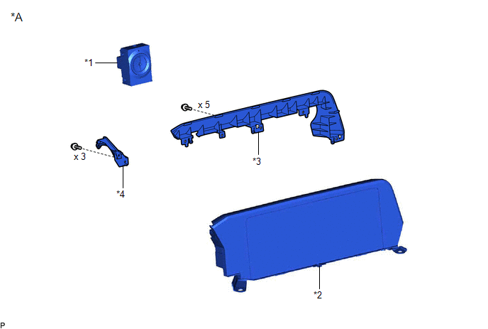
| *A | for 8 Inch Display | - | - |
| *1 | CLOCK ASSEMBLY | *2 | MULTI-DISPLAY ASSEMBLY |
| *3 | MULTI-MEDIA MODULE COVER | *4 | NO. 1 SUB-CLUSTER MODULE PANEL |
ILLUSTRATION
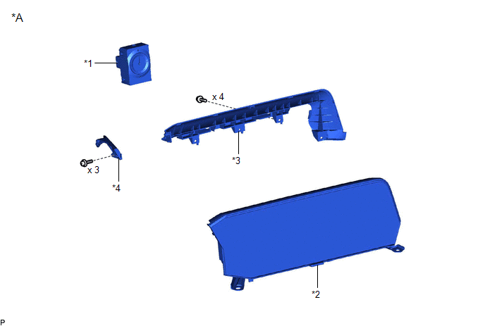
| *A | for 12.3 Inch Display | - | - |
| *1 | CLOCK ASSEMBLY | *2 | MULTI-DISPLAY ASSEMBLY |
| *3 | MULTI-MEDIA MODULE COVER | *4 | NO. 1 SUB-CLUSTER MODULE PANEL |
READ NEXT:
 Installation
INSTALLATION PROCEDURE 1. INSTALL MULTI-DISPLAY ASSEMBLY 2. INSTALL CLOCK ASSEMBLY Click here 3. INSTALL MULTI-MEDIA MODULE COVER (a) for 8 Inch Display: (1) Engage the 6 guides and 3 claws as shown
Removal
REMOVAL PROCEDURE 1. REMOVE FRONT DOOR SCUFF PLATE LH Click here 2. REMOVE COWL SIDE TRIM BOARD LH Click here 3. REMOVE FRONT DOOR OPENING TRIM COVER LH Click here 4. REMOVE INSTRUMENT SIDE PANE
SEE MORE:
Front Passenger Side Power Mirror cannot be Adjusted with Power Mirror Switch
DESCRIPTION The outer mirror switch assembly sends the mirror adjust switch signals to the main body ECU (multiplex network body ECU). The main body ECU (multiplex network body ECU) then sends the received mirror adjust switch signals to the outer mirror control ECU assembly (front passenger door) v
Generator Temperature Sensor Voltage Out of Range (P0A361C,P0A361F)
DTC SUMMARY MALFUNCTION DESCRIPTION These DTCs are stored when the generator temperature sensor output is abnormal. The cause of this malfunction may be one of the following: Generator temperature sensor malfunction
Internal generator temperature sensor malfunction
Open or short in generator te
