Lexus ES: Components
COMPONENTS
ILLUSTRATION
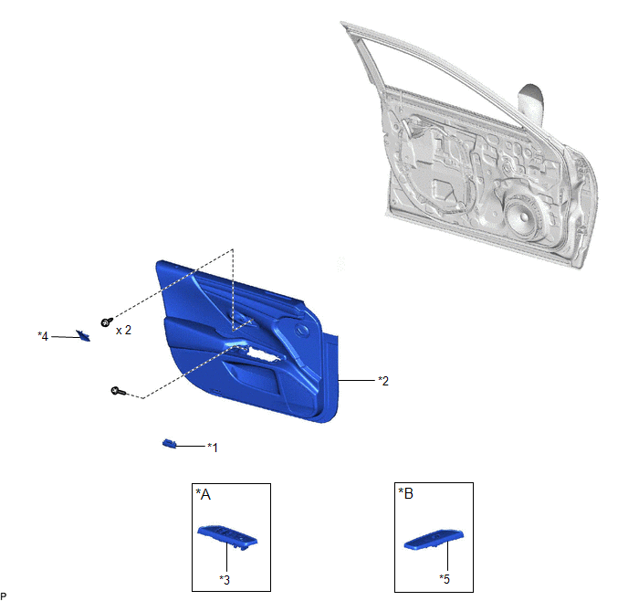
| *A | for Driver Side | *B | for Front Passenger Side |
| *1 | COURTESY LIGHT ASSEMBLY | *2 | FRONT DOOR TRIM BOARD SUB-ASSEMBLY |
| *3 | MULTIPLEX NETWORK MASTER SWITCH ASSEMBLY WITH FRONT DOOR UPPER ARMREST BASE PANEL | *4 | NO. 2 DOOR TRIM PAD |
| *5 | POWER WINDOW REGULATOR SWITCH ASSEMBLY WITH FRONT DOOR UPPER ARMREST BASE PANEL | - | - |
ILLUSTRATION
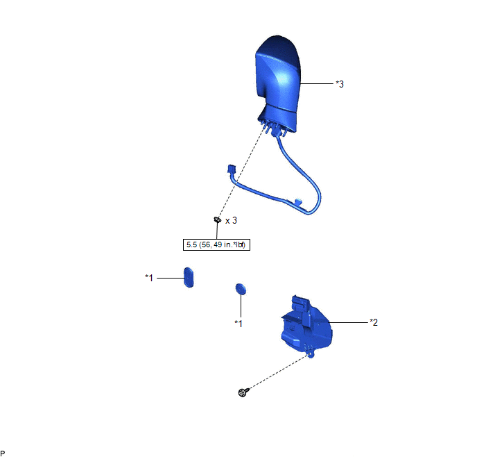
| *1 | HOLE PLUG | *2 | OUTER MIRROR INSTALL HOLE COVER |
| *3 | OUTER REAR VIEW MIRROR ASSEMBLY | - | - |
.png) | N*m (kgf*cm, ft.*lbf): Specified torque | - | - |
ILLUSTRATION
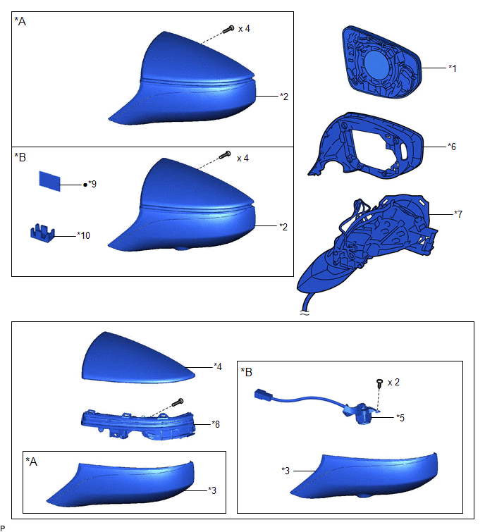
| *A | w/o Panoramic View Monitor System | *B | w/ Panoramic View Monitor System |
| *1 | OUTER MIRROR | *2 | OUTER MIRROR COVER ASSEMBLY |
| *3 | OUTER MIRROR LOWER COVER | *4 | OUTER MIRROR UPPER COVER |
| *5 | SIDE TELEVISION CAMERA ASSEMBLY | *6 | VISOR COVER ASSEMBLY |
| *7 | OUTER MIRROR RETRACTOR | *8 | SIDE TURN SIGNAL LIGHT ASSEMBLY |
| *9 | OUTER MIRROR TAPE | *10 | CAMERA CONNECTOR CLAMP |
| ● | Non-reusable part | - | - |
READ NEXT:
 Removal
REMOVAL CAUTION / NOTICE / HINT The necessary procedures (adjustment, calibration, initialization, or registration) that must be performed after parts are removed and installed, or replaced during out
Disassembly
DISASSEMBLY CAUTION / NOTICE / HINT HINT:
Use the same procedure for the RH side and LH side.
The following procedure is for the LH side.
PROCEDURE 1. REMOVE OUTER MIRROR Click here 2. REMO
Inspection
INSPECTION PROCEDURE 1. INSPECT OUTER REAR VIEW MIRROR ASSEMBLY RH (a) Check the operation of the mirror surface. NOTICE: If the mirror surface is fully turned to the right, left, upward or downward p
SEE MORE:
Removal
REMOVAL CAUTION / NOTICE / HINT The necessary procedures (adjustment, calibration, initialization or registration) that must be performed after parts are removed and installed, or replaced during VVT sensor removal/installation are shown below. Necessary Procedures After Parts Removed/Installed/Repl
High Voltage Power Resource Circuit Consumption Circuit Short (P1C8149,P1C8249)
DTC SUMMARY MALFUNCTION DESCRIPTION The hybrid vehicle control ECU monitors the high-voltage wiring between the HV battery and inverter with converter assembly and detects a short circuit malfunction or high-voltage system operation malfunction. The cause of this malfunction may be one of the follow
