
Lexus ES: Inspection
INSPECTION
PROCEDURE
1. INSPECT SIDE TURN SIGNAL LIGHT ASSEMBLY LH
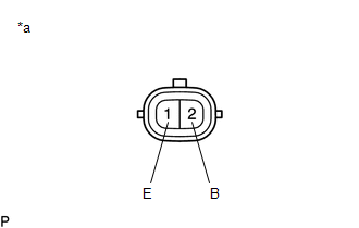
| *a | Component without harness connected (Side Turn Signal Light Assembly LH) |
(a) Apply auxiliary battery voltage to the side turn signal light assembly LH and check that the light illuminates.
OK:
| Measurement Condition | Specified Condition |
|---|---|
| Auxiliary battery positive (+) → Terminal 2 (B) Auxiliary battery negative (-) → Terminal 1 (E) | Side turn signal light illuminates |
If the result is not as specified, replace the side turn signal light assembly LH.
2. INSPECT SIDE TURN SIGNAL LIGHT ASSEMBLY RH
| *a | Component without harness connected (Side Turn Signal Light Assembly RH) |
(a) Apply auxiliary battery voltage to the side turn signal light assembly RH and check that the light illuminates.
OK:
| Measurement Condition | Specified Condition |
|---|---|
| Auxiliary battery positive (+) → Terminal 2 (B) Auxiliary battery negative (-) → Terminal 1 (E) | Side turn signal light illuminates |
If the result is not as specified, replace the side turn signal light assembly RH.
READ NEXT:
 Installation
INSTALLATION CAUTION / NOTICE / HINT HINT:
Use the same procedure for the RH side and LH side.
The following procedure is for the LH side.
PROCEDURE 1. INSTALL SIDE TURN SIGNAL LIGHT ASSEMBLY
Components
COMPONENTS ILLUSTRATION *1 NO. 1 INSTRUMENT PANEL UNDER COVER SUB-ASSEMBLY *2 STOP LIGHT SWITCH ASSEMBLY
SEE MORE:
Internal Control Module Random Access Memory (RAM) Error Data Memory Failure (P060444)
MONITOR DESCRIPTION The ECM continuously monitors its internal memory status. This self-check ensures that the ECM is functioning properly. The ECM memory status is diagnosed by internal mirroring of the main CPU and sub CPU to detect Random Access Memory (RAM) errors. If outputs from these CPUs are
Brake System Control Module "A" System Voltage System Voltage Low (C137BA2)
DESCRIPTION If a malfunction is detected in the power supply circuit, the skid control ECU (brake actuator assembly) stores this DTC and the fail-safe function prohibits ABS operation. This DTC is stored when the +BS terminal voltage meets one of the DTC detection conditions due to a malfunction in
