Lexus ES: Components
COMPONENTS
ILLUSTRATION
.png)
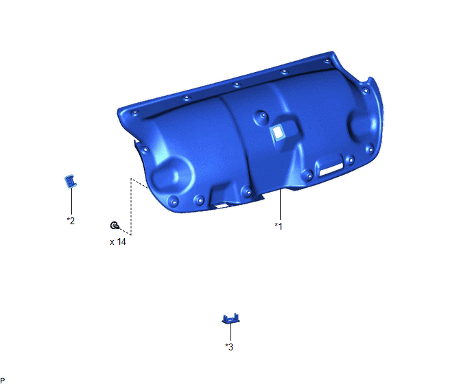
| *1 | LUGGAGE COMPARTMENT FLOOR MAT | *2 | SPARE WHEEL COVER TRAY |
ILLUSTRATION
.png)
| *1 | REAR FLOOR FINISH PLATE | *2 | LUGGAGE HOLD BELT STRIKER ASSEMBLY |
ILLUSTRATION
| *1 | LUGGAGE COMPARTMENT DOOR COVER | *2 | LUGGAGE LOCK CONTROL CABLE PLATE |
| *3 | SWITCH BEZEL | - | - |
ILLUSTRATION
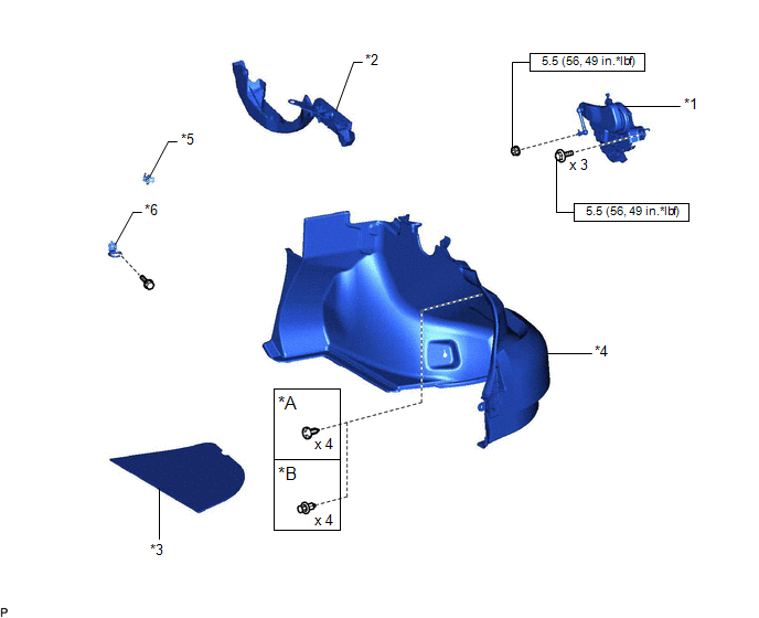
| *A | for Type A | *B | for Type B |
| *1 | LUGGAGE CLOSER MOTOR ASSEMBLY | *2 | LUGGAGE COMPARTMENT DOOR HINGE COVER RH |
| *3 | LUGGAGE COMPARTMENT TRIM COVER RH | *4 | LUGGAGE COMPARTMENT TRIM INNER COVER RH |
| *5 | ROPE HOOK | *6 | LUGGAGE HOLD BELT STRIKER ASSEMBLY |
.png) | N*m (kgf*cm, ft.*lbf): Specified torque | - | - |
ILLUSTRATION
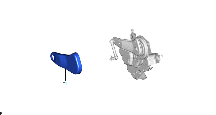
| *1 | DECK SIDE TRIM COVER RH | - | - |
READ NEXT:
 Removal
REMOVAL CAUTION / NOTICE / HINT The necessary procedures (adjustment, calibration, initialization, or registration) that must be performed after parts are removed and installed, or replaced during lug
Installation
INSTALLATION PROCEDURE 1. INSTALL DECK SIDE TRIM COVER RH (a) Engage the clip to install the deck side trim cover RH. 2. INSTALL LUGGAGE CLOSER MOTOR ASSEMBLY (a) Connect the connector. (b) Engage the
SEE MORE:
Lost Communication with Airbag System Control Module Signal Plausibility Failure (P310764)
DESCRIPTION Refer to the description for DTC P310711. Click here DTC No. Detection Item DTC Detection Condition Trouble Area MIL Warning Indicate P310764 Lost Communication with Airbag System Control Module Signal Plausibility Failure Abnormal communication signal: Communicati
Customize Parameters
CUSTOMIZE PARAMETERS CUSTOMIZE PARKING SUPPORT ALERT SYSTEM (a) Customizing with the Techstream NOTICE:
When the customer requests a change in a function, first make sure that the function can be customized.
Be sure to make a note of the current settings before customizing.
When troubleshooti
© 2016-2026 Copyright www.lexguide.net
