Lexus ES: Inspection
INSPECTION
PROCEDURE
1. INSPECT FUEL LID OPENER SWITCH (TRUNK AND FUEL SWITCH ASSEMBLY)
| (a) Check the switch. (1) Measure the resistance according to the value(s) in the table below. Standard Resistance:
If the result is not as specified, replace the fuel lid opener switch (trunk and fuel switch assembly). |
|
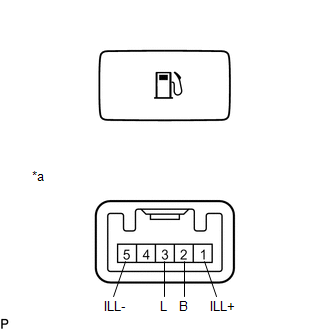
(b) Check the switch illumination.
(1) Apply auxiliary battery voltage to the switch connector and check that the fuel lid opener switch (trunk and fuel switch assembly) illuminates.
OK:
| Auxiliary Battery Condition | Specified Condition |
|---|---|
| Auxiliary battery positive (+) → Terminal 1 (ILL+) Auxiliary battery negative (-) → Terminal 5 (ILL-) | Illumination illuminates |
If the result is not as specified, replace the fuel lid opener switch (trunk and fuel switch assembly).
READ NEXT:
 Installation
INSTALLATION PROCEDURE 1. INSTALL FUEL LID OPENER SWITCH (TRUNK AND FUEL SWITCH ASSEMBLY) (a) Engage the 2 claws to install the fuel lid opener switch (trunk and fuel switch assembly) as shown in the
Precaution
PRECAUTION PRECAUTION FOR DISCONNECTING CABLE FROM NEGATIVE AUXILIARY BATTERY TERMINAL NOTICE: When disconnecting the cable from the negative (-) auxiliary battery terminal, initialize the following s
SEE MORE:
Rear Power Window RH Auto Up / Down Function does not Operate with Rear Power Window Switch RH
DESCRIPTION If the manual up and down functions operate normally but the auto up and down functions do not, the power window control system may be in fail-safe mode. If power window initialization has not been performed, the auto up and down functions will not operate. Click here WIRING DIAGRAM C
Removal
REMOVAL CAUTION / NOTICE / HINT The necessary procedures (adjustment, calibration, initialization, or registration) that must be performed after parts are removed and installed, or replaced during navigation antenna assembly removal/installation are shown below. Necessary Procedure After Parts Remov
