
Lexus ES: Components
COMPONENTS
ILLUSTRATION
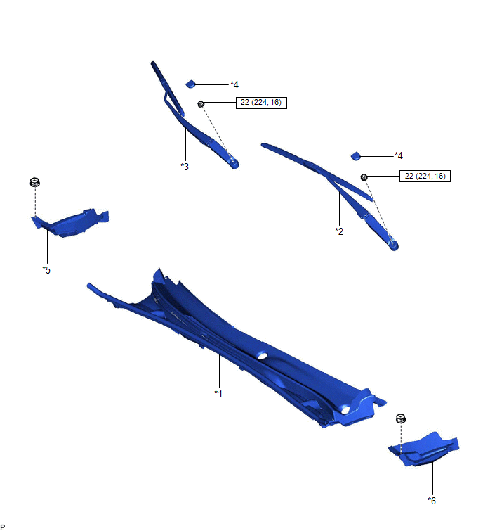
| *1 | COWL TOP VENTILATOR LOUVER SUB-ASSEMBLY | *2 | FRONT WIPER ARM AND BLADE ASSEMBLY LH |
| *3 | FRONT WIPER ARM AND BLADE ASSEMBLY RH | *4 | FRONT WIPER ARM HEAD CAP |
| *5 | NO. 2 COWL TOP PANEL INSULATOR | *6 | NO. 3 COWL TOP PANEL INSULATOR |
.png) | N*m (kgf*cm, ft.*lbf): Specified torque | - | - |
ILLUSTRATION
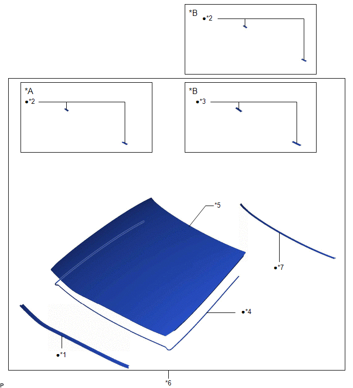
| *A | for 1-piece Type | *B | for 2-piece Type |
| *1 | FRONT WINDOW INNER CENTER MOULDING | *2 | NO. 1 WINDSHIELD GLASS STOPPER |
| *3 | NO. 2 WINDSHIELD GLASS STOPPER | *4 | WINDOW GLASS ADHESIVE DAM |
| *5 | WINDSHIELD GLASS | *6 | WINDSHIELD GLASS SUB-ASSEMBLY |
| *7 | WINDSHIELD OUTSIDE MOULDING | - | - |
| ● | Non-reusable part | - | - |
READ NEXT:
 Removal
REMOVAL CAUTION / NOTICE / HINT The necessary procedures (adjustment, calibration, initialization or registration) that must be performed after parts are removed and installed, or replaced during wind
Installation
INSTALLATION CAUTION / NOTICE / HINT NOTICE: When replacing the windshield glass of a vehicle equipped with a forward recognition camera, make sure to use a Lexus genuine part. If a non-Lexus genuine
SEE MORE:
High Mounted Stop Light Assembly
ComponentsCOMPONENTS ILLUSTRATION *1 CENTER STOP LIGHT SET - - RemovalREMOVAL PROCEDURE 1. REMOVE CENTER STOP LIGHT SET (a) Disengage the 4 guides as shown in the illustration. Disengage in this Direction (b) Turn the center stop light set as shown in the illustration.
Brake Control Warning Light Remains ON
DESCRIPTION The skid control ECU (brake booster with master cylinder assembly) is connected to the combination meter assembly via CAN communication. If the skid control ECU (brake booster with master cylinder assembly) stores a DTC, the brake warning light / yellow (minor malfunction) comes on in th
© 2016-2026 Copyright www.lexguide.net
