Lexus ES: Removal
REMOVAL
CAUTION / NOTICE / HINT
The necessary procedures (adjustment, calibration, initialization or registration) that must be performed after parts are removed and installed, or replaced during windshield glass sub-assembly removal/installation are shown below.
Necessary Procedure After Parts Removed/Installed/Replaced (for HV Model)| Replaced Part or Performed Procedure | Necessary Procedure | Effect/Inoperative Function when Necessary Procedure not Performed | Link |
|---|---|---|---|
|
*1: When performing learning using the Techstream.
Click here *2: w/ Garage Door Opener System *3: One Time Recognition *4: Sequential Recognition | |||
| Disconnect cable from negative (-) auxiliary battery terminal | Perform steering sensor zero point calibration | Lane Control System (for HV Model) | |
| Pre-collision System (for HV Model) | |||
| Parking Support Brake System (for HV Model)*1 | |||
| Lighting System (for HV Model) | |||
| Memorize steering angle neutral point | Parking Assist Monitor System (for HV Model) | | |
| Panoramic View Monitor System (for HV Model) | | ||
| Initialize power trunk lid system | Power Trunk Lid System (for HV Model) | | |
| Adjust forward recognition camera HINT: Forward recognition camera adjustment can be performed by using either One Time Recognition or Sequential Recognition. |
| |
| Inner rear view mirror assembly*2 | Register codes in the garage door opener system | Garage door opener system | |
NOTICE:
- After the power switch is turned off, the radio receiver assembly records various types of memory and settings. As a result, after turning the power switch off, make sure to wait at least 85 seconds before disconnecting the cable from the negative (-) auxiliary battery terminal. (for Audio and Visual System)
- After the power switch is turned off, the radio receiver assembly records various types of memory and settings. As a result, after turning the power switch off, make sure to wait at least 85 seconds before disconnecting the cable from the negative (-) auxiliary battery terminal. (for Navigation System)
CAUTION:
Some of these service operations affect the SRS airbag system. Read the precautionary notices concerning the SRS airbag system before servicing.
.png)
Click here .gif)
| Replaced Part or Performed Procedure | Necessary Procedure | Effect/Inoperative Function when Necessary Procedure not Performed | Link |
|---|---|---|---|
|
*1: When performing learning using the Techstream.
Click here *2: w/ Garage Door Opener System *3: One Time Recognition *4: Sequential Recognition | |||
| Disconnect cable from negative (-) battery terminal | Perform steering sensor zero point calibration | Lane Control System (for Gasoline Model) | |
| Pre-collision System (for Gasoline Model) | |||
| Parking Support Brake System (for Gasoline Model)*1 | |||
| Lighting System (for Gasoline Model) | |||
| Memorize steering angle neutral point | Parking Assist Monitor System (for Gasoline Model) | | |
| Panoramic View Monitor System (for Gasoline Model) | | ||
| Initialize power trunk lid system | Power Trunk Lid System (for Gasoline Model) | | |
| Adjust forward recognition camera HINT: Forward recognition camera adjustment can be performed by using either One Time Recognition or Sequential Recognition. |
| |
| Inner rear view mirror assembly*2 | Register codes in the garage door opener system | Garage door opener system | |
NOTICE:
- After the engine switch is turned off, the radio receiver assembly records various types of memory and settings. As a result, after turning the engine switch off, make sure to wait at least 85 seconds before disconnecting the cable from the negative (-) battery terminal. (for Audio and Visual System)
- After the engine switch is turned off, the radio receiver assembly records various types of memory and settings. As a result, after turning the engine switch off, make sure to wait at least 85 seconds before disconnecting the cable from the negative (-) battery terminal. (for Navigation System)
CAUTION:
Some of these service operations affect the SRS airbag system. Read the precautionary notices concerning the SRS airbag system before servicing.
Click here
NOTICE:
When replacing the windshield glass of a vehicle equipped with a forward recognition camera, make sure to use a Lexus genuine part. If a non-Lexus genuine part is used, the forward recognition camera may not be able to be installed due to a missing bracket. Also, the dynamic radar cruise control system, front camera system, lane control system, road sign assist system, pre-collision system or lighting system (EXT) may not operate properly due to a difference in the transmissivity or black ceramic border.
PROCEDURE
1. REMOVE WINDSHIELD OUTSIDE MOULDING LH
Click here
2. REMOVE WINDSHIELD OUTSIDE MOULDING RH
HINT:
Use the same procedure as for the LH side.
3. REMOVE FRONT WIPER ARM HEAD CAP
Click here
4. REMOVE FRONT WIPER ARM AND BLADE ASSEMBLY LH
Click here
5. REMOVE FRONT WIPER ARM AND BLADE ASSEMBLY RH
Click here
6. REMOVE NO. 3 COWL TOP PANEL INSULATOR
Click here
7. REMOVE NO. 2 COWL TOP PANEL INSULATOR
Click here
8. REMOVE COWL TOP VENTILATOR LOUVER SUB-ASSEMBLY
Click here
9. REMOVE INNER REAR VIEW MIRROR ASSEMBLY
Click here
10. REMOVE FORWARD RECOGNITION CAMERA
Click here
11. REMOVE AIR CONDITIONING THERMISTOR ASSEMBLY
Click here
12. REMOVE ROOF HEADLINING ASSEMBLY
Click here
13. REMOVE WINDSHIELD GLASS SUB-ASSEMBLY
(a) w/ Windshield Deicer System:
(1) Disconnect the connector.
(b) Apply protective tape to the area around the installation position of the windshield glass sub-assembly on the vehicle body to prevent it from being scratched.
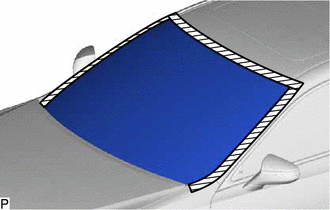
.png) | Protective Tape |
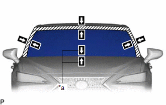
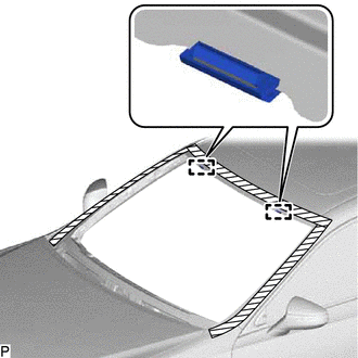
| (c) Place matchmarks on the windshield glass sub-assembly and vehicle body at the locations indicated in the illustration. HINT: Matchmarks are not necessary if the windshield glass is not going to be reused. |
|
(d) When using a windshield knife:
(1) Apply soapy water to the area around the adhesive.
(2) Insert a windshield knife into the adhesive between the windshield glass sub-assembly and vehicle body.
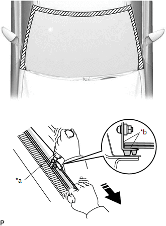
| *a | Windshield Knife |
| *b | Aligned with Windshield Glass Sub-assembly |
.png) | Pull |
(3) While keeping the windshield knife perpendicular to the outer surface of the windshield glass sub-assembly, cut the adhesive by pulling the windshield knife around the windshield glass sub-assembly.
NOTICE:
- Do not pry the windshield glass sub-assembly with the windshield knife.
- Do not use a windshield knife to cut the adhesive on the lower side of the windshield glass sub-assembly.
- When separating the windshield glass sub-assembly, be careful not to damage the paint or interior and exterior ornaments.
HINT:
Insert the windshield knife in an area where the gap between windshield glass sub-assembly and vehicle body is large.
(e) When using piano wire:
| (1) Pass a piano wire between the vehicle body and windshield glass sub-assembly from the interior. |
|

(2) Tie both wire ends to wooden blocks or similar objects that can serve as handles.
(3) Cut the adhesive by pulling the piano wire around the windshield glass sub-assembly.
NOTICE:
- When separating the windshield glass sub-assembly, be careful not to damage the paint or interior and exterior ornaments.
- To prevent the safety pad from being scratched when removing the windshield glass sub-assembly, place a plastic sheet between the piano wire and safety pad.
- Be careful not to damage the front window inner center moulding.
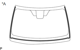
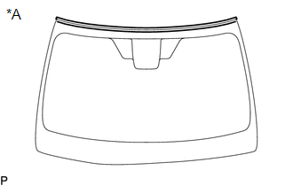
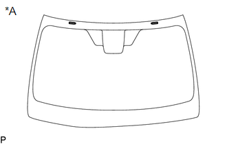
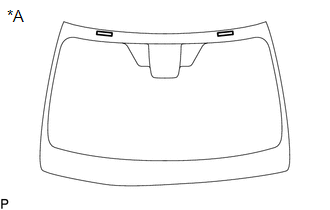
(f) Disengage the windshield glass stoppers.
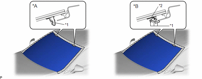
| *A | for 1-piece Type | *B | for 2-piece Type |
| *1 | No. 1 Windshield Glass Stopper | *2 | No. 2 Windshield Glass Stopper |
NOTICE:
- The No. 1 windshield glass stoppers and No. 2 windshield glass stoppers are installed to the windshield glass sub-assembly as shown in the illustration. Be careful not to damage the windshield glass sub-assembly when cutting the adhesive.
- To prevent the windshield glass sub-assembly from falling when performing this operation, be sure to hold the windshield glass sub-assembly using suction cups.
HINT:
Depending on the vehicle, either 1-piece type or 2-piece type stoppers may be present.
(g) Using suction cups, remove the windshield glass sub-assembly.
NOTICE:
- Be careful not to drop the windshield glass sub-assembly.
- Leave as much adhesive on the vehicle body as possible when removing the windshield glass sub-assembly.
14. REMOVE WINDOW GLASS ADHESIVE DAM
(a) When reusing the windshield glass:
| (1) Using a scraper, remove the window glass adhesive dam. NOTICE:
|
|
15. REMOVE WINDSHIELD OUTSIDE MOULDING
(a) When reusing the windshield glass:
| (1) Using a scraper, remove the windshield outside moulding. NOTICE:
|
|
16. REMOVE NO. 1 WINDSHIELD GLASS STOPPER (for 1-piece Type)
(a) When reusing the windshield glass:
| (1) Using a scraper, remove the 2 No. 1 windshield glass stoppers. NOTICE:
|
|
17. REMOVE NO. 2 WINDSHIELD GLASS STOPPER (for 2-piece Type)
(a) When reusing the windshield glass:
| (1) Using a scraper, remove the 2 No. 2 windshield glass stoppers. NOTICE:
|
|
18. REMOVE NO. 1 WINDSHIELD GLASS STOPPER (for 2-piece Type)
| (a) Remove the 2 No. 1 windshield glass stoppers from the vehicle body. NOTICE: Be sure to replace the No. 1 windshield glass stoppers with new ones. |
|
19. REMOVE FRONT WINDOW INNER CENTER MOULDING
HINT:
Perform the following procedure only when replacement of the front window inner center moulding is necessary.
| (a) Place matchmarks on the windshield glass at the locations indicated in the illustration. |
|
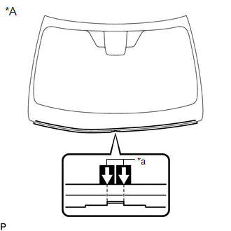
(b) Using a scraper, remove the front window inner center moulding.
NOTICE:
- Be careful not to damage the windshield glass.
- Be sure to replace the front window inner center moulding with a new one.
20. CLEAN WINDSHIELD GLASS
(a) When reusing the windshield glass:
| (1) Using a scraper, remove any remaining adhesive dam and adhesive residue from the windshield glass. NOTICE: Be careful not to damage the windshield glass. |
|
.png)
(2) Clean the outer circumference of the windshield glass with a non-residue solvent.
NOTICE:
- Do not touch the windshield glass surface after cleaning it.
- Even if using a new windshield glass, clean it with a non-residue solvent.
21. CLEAN VEHICLE BODY
(a) Clean and shape the contact surface of the vehicle body.
(1) Using a knife, cut off any excess adhesive on the contact surface of the vehicle body as shown in the illustration.
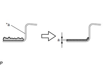
| *a | Vehicle Body |
| | Adhesive |
Standard Dimension:
| Area | Dimension |
|---|---|
| a | 1.0 mm (0.0394 in.) or more |
NOTICE:
Be careful not to damage the vehicle body.
HINT:
Leave approximately 1.0 mm (0.0394 in.) of adhesive on the vehicle body.
(2) Clean the contact surface of the vehicle body with a piece of cloth saturated with non-residue solvent.
HINT:
Even if all of the adhesive has been removed, clean the vehicle body.
READ NEXT:
 Installation
INSTALLATION CAUTION / NOTICE / HINT NOTICE: When replacing the windshield glass of a vehicle equipped with a forward recognition camera, make sure to use a Lexus genuine part. If a non-Lexus genuine
SEE MORE:
Inspection
INSPECTION PROCEDURE 1. INSPECT PANORAMIC VIEW MONITOR SWITCH (NO. 2 COMBINATION SWITCH ASSEMBLY) (a) Remove the panoramic view monitor switch (No. 2 combination switch assembly). Click here (b) Measure the resistance according to the value(s) in the table below. Standard Resistance: Tester
Lost Communication between Hybrid Powertrain Control Module and Active Grille Air Shutter Missing Message (U129387)
DESCRIPTION This DTC is stored if a communication malfunction occurs between the hybrid vehicle control ECU and swing grille actuator assembly. DTC No. Detection Item DTC Detection Condition Trouble Area U129387 Lost Communication between Hybrid Powertrain Control Module and Active Gr
