Lexus ES: Components
Lexus ES (XZ10) Service Manual / Audio & Visual & Telematics / Audio / Video / Front Door Speaker / Components
COMPONENTS
ILLUSTRATION
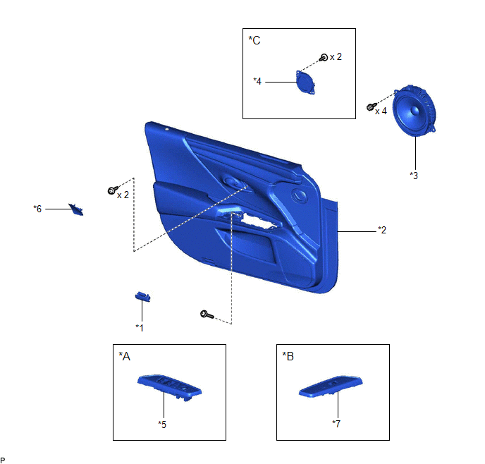
| *A | for Driver Side | *B | for Front Passenger Side |
| *C | for 17 Speakers | - | - |
| *1 | COURTESY LIGHT ASSEMBLY | *2 | FRONT DOOR TRIM BOARD SUB-ASSEMBLY |
| *3 | FRONT NO. 1 SPEAKER ASSEMBLY | *4 | FRONT NO. 4 SPEAKER ASSEMBLY |
| *5 | MULTIPLEX NETWORK MASTER SWITCH ASSEMBLY WITH FRONT DOOR UPPER ARMREST BASE PANEL | *6 | NO. 2 DOOR TRIM PAD |
| *7 | POWER WINDOW REGULATOR SWITCH ASSEMBLY WITH FRONT DOOR UPPER ARMREST BASE PANEL | - | - |
READ NEXT:
 Inspection
INSPECTION PROCEDURE 1. INSPECT FRONT NO. 1 SPEAKER ASSEMBLY (a) With the speaker installed, check that there is no looseness or other abnormalities. (b) Check that there is no foreign matter in the s
Installation
INSTALLATION CAUTION / NOTICE / HINT HINT:
Use the same procedure for the RH side and LH side.
The following procedure is for the LH side.
PROCEDURE 1. INSTALL FRONT NO. 4 SPEAKER ASSEMBLY (fo
Removal
REMOVAL CAUTION / NOTICE / HINT HINT:
Use the same procedure for the RH side and LH side.
The following procedure is for the LH side.
PROCEDURE 1. REMOVE NO. 2 DOOR TRIM PAD Click here 2.
SEE MORE:
Terminals Of Ecu
TERMINALS OF ECU CHECK SWING GRILLE ACTUATOR ASSEMBLY (a) Disconnect the z23 swing grille actuator assembly connector. (b) Measure the voltage and resistance according to the value(s) in the table below. HINT: Measure the values on the wire harness side with the connector disconnected. Tester Co
AWD Warning Remains ON
DESCRIPTION The 4WD ECU assembly is connected to the combination meter assembly via CAN communication. If the 4WD ECU assembly stores any DTCs which are related to the dynamic torque control AWD system, the warning message is displayed on the multi-information display in the combination meter assemb
© 2016-2026 Copyright www.lexguide.net
