Lexus ES: AWD Warning Remains ON
DESCRIPTION
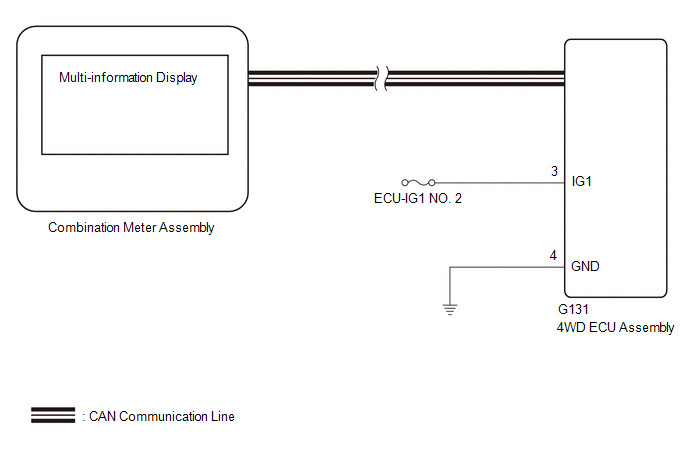
The 4WD ECU assembly is connected to the combination meter assembly via CAN communication.
If the 4WD ECU assembly stores any DTCs which are related to the dynamic torque control AWD system, the warning message is displayed on the multi-information display in the combination meter assembly.
WIRING DIAGRAM
CAUTION / NOTICE / HINT
NOTICE:
Inspect the fuses for circuits related to this system before performing the following inspection procedure.
PROCEDURE
| 1. | CHECK FOR DTC (CAN COMMUNICATION SYSTEM AND DYNAMIC TORQUE CONTROL AWD SYSTEM) |
(a) Check if CAN communication system DTCs are output.
Click here .gif)
(b) Check if the dynamic torque control AWD system DTC is output.
Chassis > Four Wheel Drive > Trouble Codes| Result | Proceed to |
|---|---|
| Neither CAN communication system DTC nor dynamic torque control AWD system DTC is output | A |
| CAN communication system DTC is output | B |
| Dynamic torque control AWD system DTC is output | C |
HINT:
When DTCs indicating a CAN communication system malfunction are output, repair the CAN communication system before repairing each corresponding sensor.
| B | .gif) | GO TO CAN COMMUNICATION SYSTEM (HOW TO PROCEED WITH TROUBLESHOOTING) |
| C | | REPAIR CIRCUIT INDICATED BY OUTPUT CODE (DYNAMIC TORQUE CONTROL AWD SYSTEM) |
|
.gif)
| 2. | CHECK IF 4WD ECU ASSEMBLY CONNECTOR IS SECURELY CONNECTED |
(a) Check if the 4WD ECU assembly connector is securely connected.
OK:
The connector is securely connected.
| NG | | CONNECT CONNECTOR TO ECU CORRECTLY |
|
| 3. | INSPECT BATTERY |
(a) Check the battery voltage.
Standard Voltage:
11 to 14 V
| NG | | CHECK CHARGING SYSTEM |
|
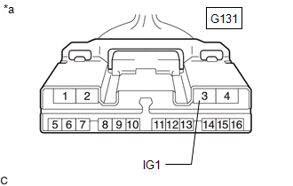
| 4. | CHECK HARNESS AND CONNECTOR (IG1 TERMINAL) |
| (a) Disconnect the G131 4WD ECU assembly connector. |
|
(b) Turn the engine switch on (IG).
(c) Measure the voltage according to the value(s) in the table below.
Standard Voltage:
| Tester Connection | Condition | Specified Condition |
|---|---|---|
| G131-3 (IG1) - Body ground | Engine switch on (IG) | 11 to 14 V |
| NG | | REPAIR OR REPLACE HARNESS OR CONNECTOR |
|
| 5. | CHECK HARNESS AND CONNECTOR (GND TERMINAL) |
(a) Turn the engine switch off.
(b) Measure the resistance according to the value(s) in the table below.
Standard Resistance:
| Tester Connection | Condition | Specified Condition |
|---|---|---|
| G131-4 (GND) - Body ground | Always | Below 1 Ω |
| NG | | REPAIR OR REPLACE HARNESS OR CONNECTOR |
|
| 6. | READ VALUE USING TECHSTREAM (4WD WARNING LIGHT) |
(a) Turn the engine switch off.
(b) Connect the Techstream the DLC3.
(c) Turn the engine switch on (IG).
(d) Turn the Techstream on.
(e) Enter the following menus: Chassis / Four Wheel Drive / Data List.
(f) According to the display on the Techstream, read the Data List.
Chassis > Four Wheel Drive > Data List| Tester Display | Measurement Item | Range | Normal Condition | Diagnostic Note |
|---|---|---|---|---|
| 4WD Warning Light | AWD warning (multi-information display) | OFF or ON | OFF: Warning off ON: Warning on | - |
| Tester Display |
|---|
| 4WD Warning Light |
(g) Check the Techstream display condition of the 4WD warning light.
| Result | Proceed to |
|---|---|
| Display of the Data List remains OFF | A |
| Display of the Data List remains ON | B |
| A | | GO TO METER / GAUGE SYSTEM (HOW TO PROCEED WITH TROUBLESHOOTING) |
| B | | REPLACE 4WD ECU ASSEMBLY |
READ NEXT:
 Linear Solenoid Power Supply System Malfunction (C120C)
DESCRIPTION This DTC is output by the 4WD ECU assembly if a malfunction occurs in the linear solenoid power supply system. DTC No. Detection Item DTC Detection Condition Trouble Area C120
Low or High Power Supply Voltage (C1241)
DESCRIPTION If a malfunction in the power source circuit occurs, or a malfunction in communication with the skid control ECU (brake actuator assembly) or in a speed sensor occurs, the 4WD ECU assembly
Engine Circuit Malfunction (C1280)
DESCRIPTION If a malfunction in the ECM circuit occurs, the 4WD ECU assembly will output this DTC. DTC No. Detection Item DTC Detection Condition Trouble Area C1280 Engine Circuit Malfu
SEE MORE:
Internal Control Module EEPROM Data Memory Failure (P062F44)
DESCRIPTION The ECM monitors its internal operation and stores this DTC when it detects an internal malfunction. DTC No. Detection Item DTC Detection Condition Trouble Area MIL Memory Note P062F44 Internal Control Module EEPROM Data Memory Failure An ECM internal error (EEPROM
Back-up Light Circuit
DESCRIPTION The hybrid vehicle control ECU controls the back-up lights via the BKUP LP relay. WIRING DIAGRAM CAUTION / NOTICE / HINT NOTICE:
Inspect the fuses for circuits related to this system before performing the following procedure.
Before replacing the hybrid vehicle control ECU, refer t
