Lexus ES: Components
COMPONENTS
ILLUSTRATION
.png)
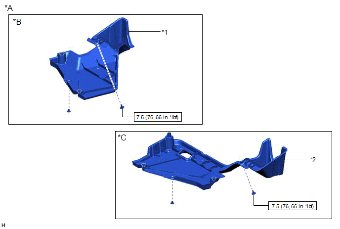
| *A | for Gasoline Model 2WD | *B | for RH Side |
| *C | for LH Side | - | - |
| *1 | NO. 1 FLOOR UNDER COVER | *2 | NO. 2 FLOOR UNDER COVER |
.png) | N*m (kgf*cm, ft.*lbf): Specified torque | - | - |
ILLUSTRATION
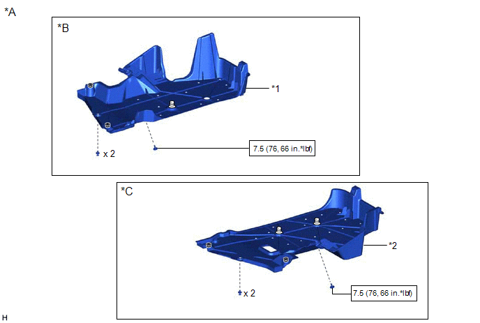
| *A | for HV Model | *B | for RH Side |
| *C | for LH Side | - | - |
| *1 | NO. 1 FLOOR UNDER COVER | *2 | NO. 2 FLOOR UNDER COVER |
| | N*m (kgf*cm, ft.*lbf): Specified torque | - | - |
ILLUSTRATION
| *A | for Gasoline Model AWD | *B | for RH Side |
| *C | for LH Side | - | - |
| *1 | NO. 1 FLOOR UNDER COVER | *2 | NO. 2 FLOOR UNDER COVER |
| | N*m (kgf*cm, ft.*lbf): Specified torque | - | - |
ILLUSTRATION
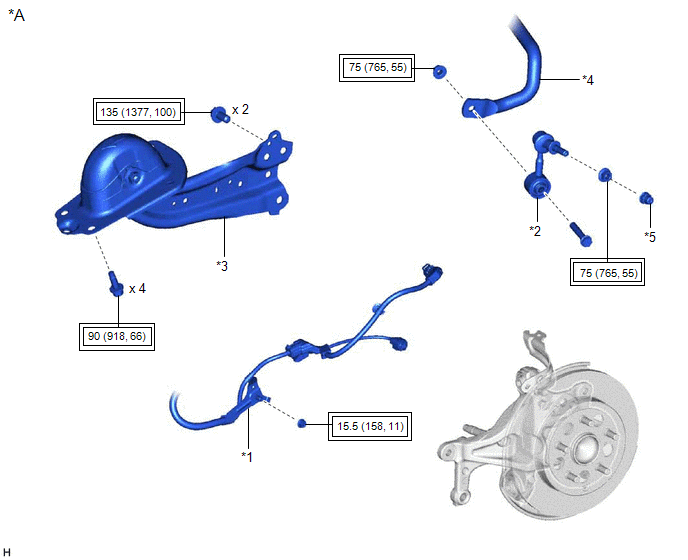
| *A | for 2WD without AVS | - | - |
| *1 | NO. 2 PARKING BRAKE WIRE ASSEMBLY | *2 | REAR STABILIZER LINK ASSEMBLY |
| *3 | REAR TRAILING ARM ASSEMBLY | *4 | REAR STABILIZER BAR |
| *5 | CAP | - | - |
.png) | Tightening torque for "Major areas involving basic vehicle performance such as moving/turning/stopping": N*m (kgf*cm, ft.*lbf) | - | - |
ILLUSTRATION
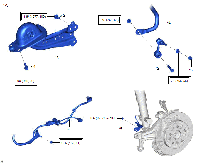
| *A | for 2WD with AVS | - | - |
| *1 | NO. 2 PARKING BRAKE WIRE ASSEMBLY | *2 | REAR STABILIZER LINK ASSEMBLY |
| *3 | REAR TRAILING ARM ASSEMBLY | *4 | REAR STABILIZER BAR |
| *5 | WIRE HARNESS BRACKET | *6 | CAP |
| | Tightening torque for "Major areas involving basic vehicle performance such as moving/turning/stopping": N*m (kgf*cm, ft.*lbf) | | N*m (kgf*cm, ft.*lbf): Specified torque |
ILLUSTRATION
| *A | for Gasoline Model AWD | - | - |
| *1 | NO. 2 PARKING BRAKE WIRE ASSEMBLY | *2 | REAR TRAILING ARM ASSEMBLY |
| | Tightening torque for "Major areas involving basic vehicle performance such as moving/turning/stopping": N*m (kgf*cm, ft.*lbf) | - | - |
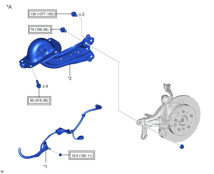
ILLUSTRATION
.png)
| *1 | REAR SUSPENSION ARM BRACKET | *2 | REAR SUSPENSION ARM COVER |
| *3 | REAR TRAILING ARM ASSEMBLY | - | - |
| | Tightening torque for "Major areas involving basic vehicle performance such as moving/turning/stopping": N*m (kgf*cm, ft.*lbf) | - | - |
READ NEXT:
 Removal
REMOVAL CAUTION / NOTICE / HINT The necessary procedures (adjustment, calibration, initialization, or registration) that must be performed after parts are removed and installed, or replaced during rea
Removal
REMOVAL CAUTION / NOTICE / HINT The necessary procedures (adjustment, calibration, initialization, or registration) that must be performed after parts are removed and installed, or replaced during rea
Installation
INSTALLATION CAUTION / NOTICE / HINT HINT:
Use the same procedure for the RH side and LH side.
The following procedure is for the LH side.
PROCEDURE 1. INSTALL REAR SUSPENSION ARM BRACKET (
SEE MORE:
Power Trunk Lid does not Operate Using Cabin Switch
DESCRIPTION The trunk and fuel switch assembly (luggage compartment door opening switch) signal is sent to the luggage closer motor assembly. If the power trunk lid does not operate using the trunk and fuel (luggage compartment door opening switch), a trunk and fuel (luggage compartment door opening
System Description
SYSTEM DESCRIPTION SLIDING ROOF SYSTEM DESCRIPTION (a) The sliding roof system controls the sliding roof operation using the sliding roof ECU (sliding roof drive gear sub-assembly). Operating the sliding roof switch (map light sub-assembly) results in electrical power being transmitted to the slidin
