Lexus ES: Components
COMPONENTS
ILLUSTRATION
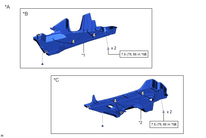
| *A | for Gasoline Model 2WD | *B | for RH Side |
| *C | for LH Side | - | - |
| *1 | NO. 1 FLOOR UNDER COVER | *2 | NO. 2 FLOOR UNDER COVER |
.png) | N*m (kgf*cm, ft.*lbf): Specified torque | - | - |
ILLUSTRATION
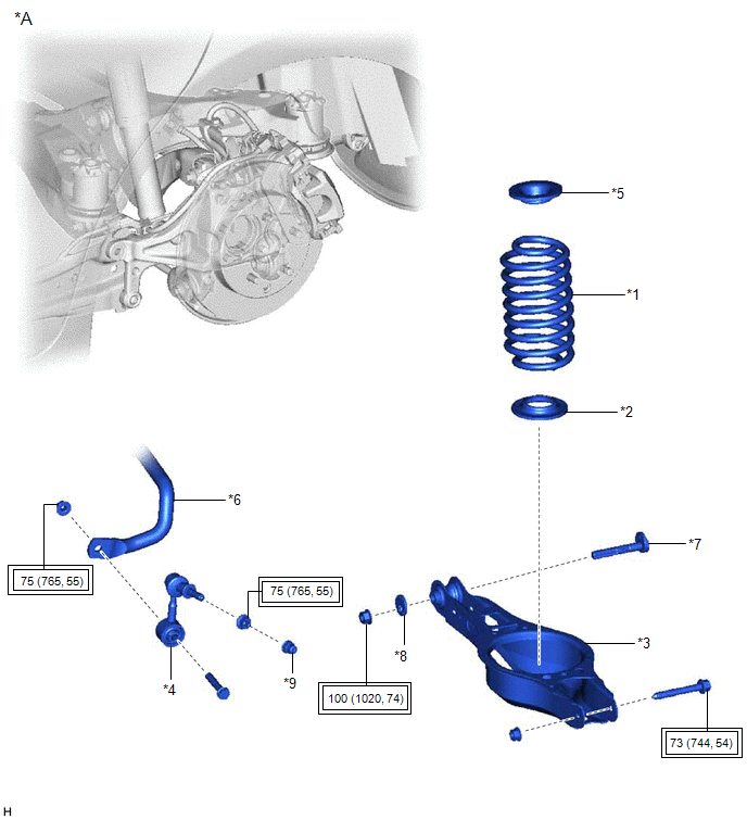
| *A | for 2WD | - | - |
| *1 | REAR COIL SPRING | *2 | REAR LOWER COIL SPRING INSULATOR |
| *3 | REAR NO. 2 SUSPENSION ARM ASSEMBLY | *4 | REAR STABILIZER LINK ASSEMBLY |
| *5 | REAR UPPER COIL SPRING INSULATOR | *6 | REAR STABILIZER BAR |
| *7 | REAR SUSPENSION TOE ADJUST CAM SUB-ASSEMBLY | *8 | NO. 2 CAMBER ADJUST CAM |
| *9 | CAP | - | - |
.png) | Tightening torque for "Major areas involving basic vehicle performance such as moving/turning/stopping": N*m (kgf*cm, ft.*lbf) | - | - |
ILLUSTRATION
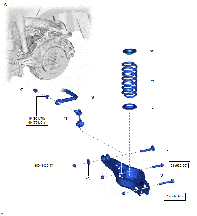
| *A | for AWD | - | - |
| *1 | REAR COIL SPRING | *2 | REAR LOWER COIL SPRING INSULATOR |
| *3 | REAR NO. 2 SUSPENSION ARM ASSEMBLY | *4 | REAR STABILIZER LINK ASSEMBLY |
| *5 | REAR SUSPENSION TOE ADJUST CAM SUB-ASSEMBLY | *6 | NO. 2 CAMBER ADJUST CAM |
| *7 | CAP | *8 | REAR STABILIZER BAR |
| | Tightening torque for "Major areas involving basic vehicle performance such as moving/turning/stopping": N*m (kgf*cm, ft.*lbf) | - | - |
READ NEXT:
 Removal
REMOVAL CAUTION / NOTICE / HINT The necessary procedures (adjustment, calibration, initialization, or registration) that must be performed after parts are removed and installed, or replaced during rea
Removal
REMOVAL CAUTION / NOTICE / HINT The necessary procedures (adjustment, calibration, initialization, or registration) that must be performed after parts are removed and installed, or replaced during rea
Installation
INSTALLATION CAUTION / NOTICE / HINT HINT:
Use the same procedure for the RH side and LH side.
The following procedure is for the LH side.
PROCEDURE 1. INSTALL REAR UPPER COIL SPRING INSULATOR
SEE MORE:
On-vehicle Inspection
ON-VEHICLE INSPECTION CAUTION / NOTICE / HINT CAUTION: To prevent injury due to contact with an operating V-ribbed belt or cooling fan, keep your hands and clothing away from the V-ribbed belt and cooling fans when working in the engine compartment with the engine running or the engine switch on (IG
Wiper Motor Power Source Circuit
DESCRIPTION This circuit is the power source circuit for the windshield wiper motor assembly. WIRING DIAGRAM CAUTION / NOTICE / HINT NOTICE:
Inspect the fuses of circuits related to this system before performing the following procedure.
Before replacing the main body ECU (multiplex network bod
