Lexus ES: Removal
REMOVAL
CAUTION / NOTICE / HINT
The necessary procedures (adjustment, calibration, initialization, or registration) that must be performed after parts are removed and installed, or replaced during rear coil spring removal/installation are shown below.
Necessary Procedures After Parts Removed/Installed/Replaced (for HV Model:)| Replaced Part or Performed Procedure | Necessary Procedure | Effect/Inoperative Function when Necessary Procedure not Performed | Link |
|---|---|---|---|
| *1: for LED type turn signal light | |||
| Suspension, tires, etc. (The vehicle height changes because of suspension or tire replacement.) |
|
| |
| Rear television camera assembly optical axis adjustment (Back camera position setting) | Parking Assist Monitor System | | |
| Panoramic View Monitor System | | |
| Perform headlight ECU sub-assembly LH initialization*1 | Lighting System | | |
| Rear height control sensor sub-assembly LH | Perform headlight ECU sub-assembly LH initialization*1 | Lighting System | |
| Rear wheel alignment adjustment |
|
| |
| Replaced Part or Performed Procedure | Necessary Procedure | Effect/Inoperative Function when Necessary Procedure not Performed | Link |
|---|---|---|---|
| *1: for LED type turn signal light | |||
| Suspension, tires, etc. (The vehicle height changes because of suspension or tire replacement.) |
|
| |
| Rear television camera assembly optical axis adjustment (Back camera position setting) | Parking Assist Monitor System | | |
| Panoramic View Monitor System | | |
| Perform headlight ECU sub-assembly LH initialization*1 | Lighting System | | |
| Rear height control sensor sub-assembly LH | Perform headlight ECU sub-assembly LH initialization*1 | Lighting System | |
| Rear wheel alignment adjustment |
|
| |
CAUTION / NOTICE / HINT
HINT:
- Use the same procedure for the RH side and LH side.
- The following procedure is for the LH side.
PROCEDURE
1. REMOVE REAR WHEEL
Click here .gif)
2. REMOVE NO. 2 FLOOR UNDER COVER (for Gasoline Model)
(a) for LH Side:
Click here
3. REMOVE NO. 1 FLOOR UNDER COVER (for Gasoline Model)
(a) for RH Side:
Click here
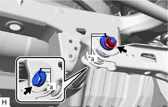
4. REMOVE REAR HEIGHT CONTROL SENSOR SUB-ASSEMBLY LH (w/ Height Control Sensor)
(a) for LH Side:
Click here
5. REMOVE REAR STABILIZER LINK ASSEMBLY
Click here
6. REMOVE REAR COIL SPRING
| (a) Place matchmarks on the No. 2 camber adjust cam, rear suspension toe adjust cam sub-assembly and rear suspension member sub-assembly. |
|
(b) Loosen the nut (rear suspension member sub-assembly side) of the rear No. 2 suspension arm assembly.
NOTICE:
Hold the rear suspension toe adjust cam sub-assembly while rotating the nut.
| (c) Using a jack and wooden block, support the rear No. 2 suspension arm assembly. NOTICE:
|
|
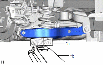
| (d) Remove the bolt and nut, and separate the rear No. 2 suspension arm assembly from the rear axle carrier sub-assembly. NOTICE: Because the nut has its own stopper, do not turn the nut. Loosen the bolt with the nut secured. |
|
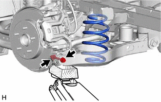
(e) Slowly lower the rear No. 2 suspension arm assembly, and then remove the rear coil spring.
7. REMOVE REAR UPPER COIL SPRING INSULATOR
(a) Remove the rear upper coil spring insulator from the vehicle.
8. REMOVE REAR LOWER COIL SPRING INSULATOR
(a) Remove the rear lower coil spring insulator from the rear No. 2 suspension arm assembly.
READ NEXT:
 Removal
REMOVAL CAUTION / NOTICE / HINT The necessary procedures (adjustment, calibration, initialization, or registration) that must be performed after parts are removed and installed, or replaced during rea
Installation
INSTALLATION CAUTION / NOTICE / HINT HINT:
Use the same procedure for the RH side and LH side.
The following procedure is for the LH side.
PROCEDURE 1. INSTALL REAR UPPER COIL SPRING INSULATOR
Installation
INSTALLATION CAUTION / NOTICE / HINT HINT:
Use the same procedure for the RH side and LH side.
The following procedure is for the LH side.
PROCEDURE 1. INSTALL REAR UPPER COIL SPRING INSULATOR
SEE MORE:
System Description
SYSTEM DESCRIPTION GENERAL The windshield deicer system uses thin heater wires attached to the inside of the windshield glass to help deice the window surface more quickly. An indicator light illuminates while the system is operating. This system automatically turns off after approximately 15 minute
Lost Communication with Cruise Control Front Distance Range Sensor Single Sensor or Center Missing Message (U023587)
DESCRIPTION The forward recognition camera communicates with the millimeter wave radar sensor assembly via CAN communication. If a communication malfunction between the forward recognition camera and millimeter wave radar sensor assembly is detected, DTC U023587 is stored. DTC No. Detection Ite
