Lexus ES: Installation
INSTALLATION
CAUTION / NOTICE / HINT
HINT:
- Use the same procedure for the RH side and LH side.
- The following procedure is for the LH side.
PROCEDURE
1. INSTALL REAR UPPER COIL SPRING INSULATOR
(a) Install the rear upper coil spring insulator to the vehicle.
2. INSTALL REAR LOWER COIL SPRING INSULATOR
(a) Install the rear lower coil spring insulator to the rear No. 2 suspension arm assembly.
3. INSTALL REAR COIL SPRING
(a) Set the rear coil spring to the rear No. 2 suspension arm assembly.
NOTICE:
- Set the rear coil spring so that its lower end is within the range shown in the illustration.
- Set the rear coil spring so that the identification mark is positioned as shown in the illustration.
- The smaller diameter end must face upward.
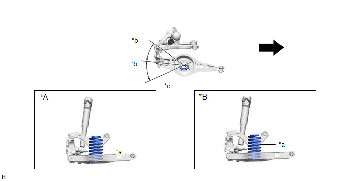 *B
*B
| *A | for TMK Made | *B | for TMMK Made |
| *a | Identification Mark | *b | 30° or less |
| *c | Lower End of Rear Coil Spring | - | - |
.png) | Inner Side of the Vehicle | - | - |
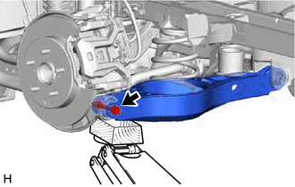
(b) Using a jack and wooden block, slowly jack up the rear No. 2 suspension arm assembly and then install the rear No. 2 suspension arm assembly to the rear axle carrier sub-assembly with the bolt and nut.
CAUTION:
Do not jack up the rear No. 2 suspension arm assembly too high as the vehicle may fall.
NOTICE:
- Because the nut has its own stopper, do not turn the nut. Tighten the bolt with the nut secured.
- When jacking up the rear No. 2 suspension arm assembly, be sure to jack it up slowly.
- Make sure to perform this operation with the vehicle kept as low as possible.
- Insert the bolt with the threaded end facing the front of the vehicle.
4. STABILIZE SUSPENSION
Click here .gif)
5. INSTALL REAR NO. 2 SUSPENSION ARM ASSEMBLY
| (a) Install the rear No. 2 suspension arm assembly (rear axle carrier sub-assembly side) with the bolt. Torque: 73 N·m {744 kgf·cm, 54 ft·lbf} NOTICE: Because the nut has its own stopper, do not turn the nut. Tighten the bolt with the nut secured. |
|
6. INSTALL REAR STABILIZER LINK ASSEMBLY
Click here
7. INSTALL NO. 1 FLOOR UNDER COVER (for Gasoline Model)
(a) for RH Side:
Click here
8. INSTALL NO. 2 FLOOR UNDER COVER (for Gasoline Model)
(a) for LH Side:
Click here
9. INSTALL REAR HEIGHT CONTROL SENSOR SUB-ASSEMBLY LH (w/ Height Control Sensor)
(a) for LH Side:
Click here
10. INSTALL REAR WHEEL
Click here
11. INSTALL REAR NO. 2 SUSPENSION ARM ASSEMBLY
(a) Install the rear No. 2 suspension arm assembly (rear suspension member sub-assembly side) with the nut.
Click here
12. INSPECT AND ADJUST REAR WHEEL ALIGNMENT
Click here
13. PERFORM INITIALIZATION
for HV Model:| *1: for LED type turn signal light | |
| |
| Parking Assist Monitor System | |
| Panoramic View Monitor System | |
| Lighting System*1 | |
| *1: for LED type turn signal light | |
| |
| Parking Assist Monitor System | |
| Panoramic View Monitor System | |
| Lighting System*1 | |
READ NEXT:
 Installation
INSTALLATION CAUTION / NOTICE / HINT HINT:
Use the same procedure for the RH side and LH side.
The following procedure is for the LH side.
PROCEDURE 1. INSTALL REAR UPPER COIL SPRING INSULATOR
Components
COMPONENTS ILLUSTRATION *A for Gasoline Model *B for RH Side *C for LH Side - - *1 NO. 1 FLOOR UNDER COVER *2 NO. 2 FLOOR UNDER COVER N*m (kgf*cm, ft.*lbf): Specif
SEE MORE:
Initialization
INITIALIZATION INITIALIZE SLIDING ROOF SYSTEM NOTICE:
When the sliding roof glass sub-assembly or sliding roof drive cable sub-assembly is adjusted or removed/installed, or the sliding roof drive gear sub-assembly is replaced, the sliding roof ECU (sliding roof drive gear sub-assembly) must be in
Luggage Compartment Door Opener Outer Switch
ComponentsCOMPONENTS ILLUSTRATION *1 LUGGAGE ELECTRICAL KEY SWITCH - - RemovalREMOVAL PROCEDURE 1. REMOVE LUGGAGE COMPARTMENT DOOR OUTSIDE GARNISH SUB-ASSEMBLY Click here 2. REMOVE LUGGAGE ELECTRICAL KEY SWITCH (a) Disconnect the connector. (b) Disengage the clamp. (c
