Lexus ES: Components
COMPONENTS
ILLUSTRATION
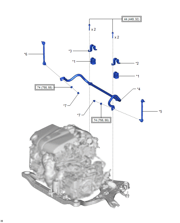
| *1 | FRONT NO. 1 STABILIZER BAR BUSHING | *2 | FRONT NO. 1 STABILIZER BRACKET LH |
| *3 | FRONT NO. 1 STABILIZER BRACKET RH | *4 | FRONT STABILIZER BAR |
| *5 | FRONT STABILIZER LINK ASSEMBLY LH | *6 | FRONT STABILIZER LINK ASSEMBLY RH |
| *7 | CAP | - | - |
.png) | Tightening torque for "Major areas involving basic vehicle performance such as moving/turning/stopping": N*m (kgf*cm, ft.*lbf) | - | - |
READ NEXT:
 Removal
REMOVAL CAUTION / NOTICE / HINT The necessary procedures (adjustment, calibration, initialization, or registration) that must be performed after parts are removed and installed, or replaced during fro
Inspection
INSPECTION PROCEDURE 1. INSPECT FRONT STABILIZER LINK ASSEMBLY (a) Inspect the turning torque of the ball joint. (1) Secure the front stabilizer link assembly in a vise using aluminum plates. NOTIC
Installation
INSTALLATION PROCEDURE 1. INSTALL FRONT NO. 1 STABILIZER BAR BUSHING (for LH Side) (a) Install the front No. 1 stabilizer bar bushing to the front stabilizer bar as shown in the illustration. *a
SEE MORE:
Parts Location
PARTS LOCATION ILLUSTRATION *1 DEICER RELAY *2 NO. 2 ENGINE ROOM RELAY BLOCK AND NO. 2 ENGINE ROOM JUNCTION BLOCK ASSEMBLY - DEICER FUSE *3 MULTI-DISPLAY ASSEMBLY - FRONT WIPER DEICER SWITCH *4 WINDSHIELD DEICER WIRE (WINDSHIELD GLASS) *5 DLC3 *6 AIR CONDITIONING AMPLIF
Customize Parameters
CUSTOMIZE PARAMETERS NOTICE:
When the customer requests a change in a function, first make sure that the function can be customized.
Be sure to make a note of the current settings before customizing.
When troubleshooting a function, first make sure that the function is set to the default sett
© 2016-2026 Copyright www.lexguide.net
