Lexus ES: System Voltage (BATT) Circuit Short to Ground or Open (P056014)
DESCRIPTION
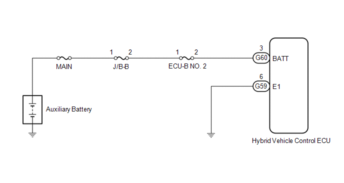
Auxiliary battery power is supplied to the BATT terminal of the hybrid vehicle control ECU in order to store DTCs and freeze frame data. Even if the power switch is turned off, back-up power is supplied.
| DTC No. | Detection Item | DTC Detection Condition | Trouble Area | MIL | Warning Indicate |
|---|---|---|---|---|---|
| P056014 | System Voltage (BATT) Circuit Short to Ground or Open | Malfunction in the hybrid vehicle control ECU back-up power source circuit (1 trip detection logic) |
| Comes on | Master Warning Light: Comes on |
MONITOR DESCRIPTION
If a period of time has elapsed with a low voltage at the BATT terminal of the hybrid vehicle control ECU, the hybrid vehicle control ECU will determine that a malfunction has occurred in the back-up power supply system, and it will store a DTC. The MIL will illuminate the next time the power switch on (IG).
MONITOR STRATEGY
| Related DTCs | P0562 (INF P056014): System voltage range check (Low voltage) |
| Required sensors/components | Main: Back-up power source circuit Sub: Hybrid vehicle control ECU |
| Frequency of operation | Continuous |
| Duration | TMC's intellectual property |
| MIL operation | Immediately |
| Sequence of operation | None |
TYPICAL ENABLING CONDITIONS
| The monitor will run whenever the following DTCs are not stored | TMC's intellectual property |
| Other conditions belong to TMC's intellectual property | - |
TYPICAL MALFUNCTION THRESHOLDS
| TMC's intellectual property | - |
COMPONENT OPERATING RANGE
| Auxiliary battery voltage | Between 9 and 14 V |
CONFIRMATION DRIVING PATTERN
HINT:
-
After repair has been completed, clear the DTC and then check that the vehicle has returned to normal by performing the following All Readiness check procedure.
Click here
.gif)
-
When clearing the permanent DTCs, refer to the "CLEAR PERMANENT DTC" procedure.
Click here
- Connect the Techstream to the DLC3.
- Turn the power switch on (IG) and turn the Techstream on.
- Clear the DTCs (even if no DTCs are stored, perform the clear DTC procedure).
- Turn the power switch off and wait for 2 minutes or more.
- Turn the power switch on (IG) and turn the Techstream on.
-
With power switch on (IG) and wait for 5 seconds or more. [*1]
HINT:
[*1] : Normal judgment procedure.
The normal judgment procedure is used to complete DTC judgment and also used when clearing permanent DTCs.
- Enter the following menus: Powertrain / Hybrid Control / Utility / All Readiness.
-
Check the DTC judgment result.
HINT:
- If the judgment result shows NORMAL, the system is normal.
- If the judgment result shows ABNORMAL, the system has a malfunction.
- If the judgment result shows INCOMPLETE or N/A, perform the normal judgment procedure again.
WIRING DIAGRAM
CAUTION / NOTICE / HINT
NOTICE:
After turning the power switch off, waiting time may be required before disconnecting the cable from the negative (-) auxiliary battery terminal. Therefore, make sure to read the disconnecting the cable from the negative (-) auxiliary battery terminal notices before proceeding with work.
Click here
PROCEDURE
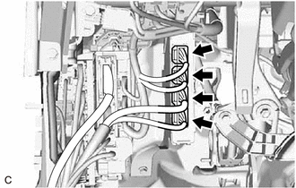
| 1. | CHECK CONNECTOR CONNECTION CONDITION (HYBRID VEHICLE CONTROL ECU CONNECTOR) |
| (a) Check the connector connections and contact pressure of the relevant terminals for the hybrid vehicle control ECU connectors. Click here OK: The connectors are connected securely and there are no contact pressure problems. |
|
| NG | .gif) | CONNECT SECURELY |
|
.gif)
| 2. | CHECK HARNESS AND CONNECTOR (HYBRID VEHICLE CONTROL ECU - ECU-B NO. 2 FUSE) |
(a) Turn the power switch off.
| (b) Measure the voltage according to the value(s) in the table below. Standard Voltage:
|
|
| OK | | REPLACE HYBRID VEHICLE CONTROL ECU |
|
| 3. | CHECK FUSE (ECU-B NO. 2) |
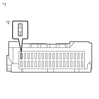
| (a) Remove the ECU-B NO. 2 fuse from the instrument panel junction block assembly. |
|
(b) Measure the resistance according to the value(s) in the table below.
Standard Resistance:
| Tester Connection | Condition | Specified Condition |
|---|---|---|
| ECU-B NO. 2 fuse | Always | Below 1 Ω |
(c) Reinstall the ECU-B NO. 2 fuse.
| NG | | REPLACE FUSE (ECU-B NO. 2) |
|
| 4. | CHECK HARNESS AND CONNECTOR (ECU-B NO. 2 FUSE - AUXILIARY BATTERY TERMINAL) |
(a) Remove the ECU-B NO. 2 fuse from the instrument panel junction block assembly.
(b) Disconnect the cable from the negative (-) auxiliary battery terminal.
(c) Disconnect the cable from the positive (+) auxiliary battery terminal.
| (d) Measure the resistance according to the value(s) in the table below. Standard Resistance:
|
|
(e) Reconnect the cable to the positive (+) auxiliary battery terminal.
(f) Reconnect the cable to the negative (-) auxiliary battery terminal.
(g) Reinstall the ECU-B NO. 2 fuse.
| NG | | REPAIR OR REPLACE HARNESS OR CONNECTOR |
|
| 5. | CHECK HARNESS AND CONNECTOR (ECU-B NO. 2 FUSE - HYBRID VEHICLE CONTROL ECU) |
(a) Remove the ECU-B NO. 2 fuse from the instrument panel junction block assembly.
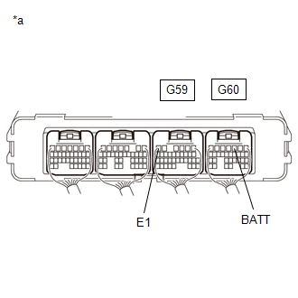
(b) Disconnect the G60 hybrid vehicle control ECU connector.
(c) Measure the resistance according to the value(s) in the table below.
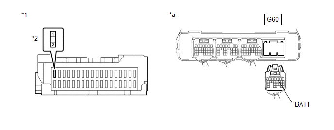
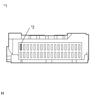
| *1 | Instrument Panel Junction Block Assembly | *2 | ECU-B NO. 2 Fuse Holder |
| *a | Rear view of wire harness connector (to Hybrid Vehicle Control ECU) | - | - |
Standard Resistance:
| Tester Connection | Condition | Specified Condition |
|---|---|---|
| 2 (ECU-B NO. 2 fuse holder) - G60-3 (BATT) | Power switch off | Below 1 Ω |
(d) Reconnect the G60 hybrid vehicle control ECU connector.
(e) Reinstall the ECU-B NO. 2 fuse.
| OK | | REPLACE HYBRID VEHICLE CONTROL ECU |
| NG | | REPAIR OR REPLACE HARNESS OR CONNECTOR |
READ NEXT:
 Hybrid/EV Powertrain Control Module Processor Watchdog / Safety MCU Failure (P060647,...,P1CE371)
DESCRIPTION The hybrid vehicle control ECU monitors its internal operation and will store these DTCs when it detects an internal malfunction. If these DTCs are output, replace the hybrid vehicle contr
Hybrid/EV Powertrain Control Module Processor Unexpected Operation (P060694)
DTC SUMMARY MALFUNCTION DESCRIPTION The main CPU and sub CPU of the Hybrid vehicle control ECU monitor each other. The cause of this malfunction may be the following: Hybrid vehicle control ECU inter
Hybrid/EV Powertrain Control Module Monitoring Processor Unexpected Operation (P060A94)
DTC SUMMARY MALFUNCTION DESCRIPTION The main CPU and sub CPU of the hybrid vehicle control ECU monitor their internal operation and each other for malfunctions. The cause of this malfunction may be th
SEE MORE:
Front Camera Feedback Malfunction (C1681)
DESCRIPTION DTC C1681 is stored if the parking assist ECU judges as a result of its self check that a synchronization problem is occurring in the image signal sent from the front television camera assembly to the parking assist ECU. DTC No. Detection Item DTC Detection Condition Trouble Are
VSC OFF Switch Circuit
DESCRIPTION The skid control ECU (brake actuator assembly) is connected to the combination meter assembly via CAN communication. Pressing the VSC OFF switch turns off TRAC operation, and pressing and holding this switch turns off TRAC and VSC operation. If TRAC and VSC operations are turned off, "Tr
