Lexus ES: Components
COMPONENTS
ILLUSTRATION
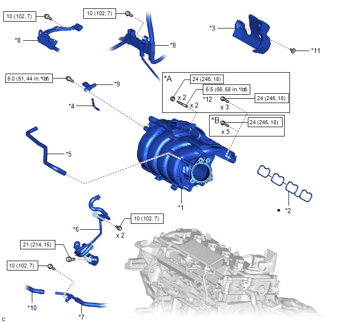
| *A | w/ Stud Bolt | *B | w/o Stud Bolt |
| *1 | INTAKE MANIFOLD | *2 | NO. 1 INTAKE MANIFOLD TO HEAD GASKET |
| *3 | NO. 1 ENGINE COVER | *4 | VACUUM HOSE |
| *5 | NO. 2 FUEL VAPOR FEED HOSE | *6 | NO. 2 WATER BY-PASS PIPE |
| *7 | NO. 3 WATER BY-PASS PIPE | *8 | ENGINE WIRE |
| *9 | E.F.I. VACUUM SENSOR ASSEMBLY (MANIFOLD ABSOLUTE PRESSURE SENSOR) | *10 | NO. 5 WATER BY-PASS HOSE |
| *11 | CLIP | *12 | STUD BOLT |
.png) | N*m (kgf*cm, ft.*lbf): Specified torque | ● | Non-reusable part |
READ NEXT:
 Removal
REMOVAL CAUTION / NOTICE / HINT The necessary procedures (adjustment, calibration, initialization or registration) that must be performed after parts are removed and installed, or replaced during inta
Installation
INSTALLATION CAUTION / NOTICE / HINT NOTICE: This procedure includes the installation of small-head bolts. Refer to Small-Head Bolts of Basic Repair Hint to identify the small-head bolts. Click here
Intake System
On-vehicle InspectionON-VEHICLE INSPECTION CAUTION / NOTICE / HINT The necessary procedures (adjustment, calibration, initialization or registration) that must be performed after parts are removed an
SEE MORE:
Open in One Side of Bus 4 Branch Line
DESCRIPTION When the CAN bus main lines are normal (no open, short to ground, short to +B or short between lines) and there is an ECU or sensor on the "Communication Bus Check" screen that is indicated as not communicating or whose connection status on the "Communication Bus Check" screen changes in
Diagnosis System
DIAGNOSIS SYSTEM DESCRIPTION (a) When troubleshooting On-Board Diagnostic (OBD II) vehicles, an OBD II scan tool (complying with SAE J1978) must be connected to the vehicle. Various data output from the vehicle ECM can then be read. (b) OBD II regulations require that the vehicle on-board computer i
© 2016-2026 Copyright www.lexguide.net
