Lexus ES: Components
COMPONENTS
ILLUSTRATION
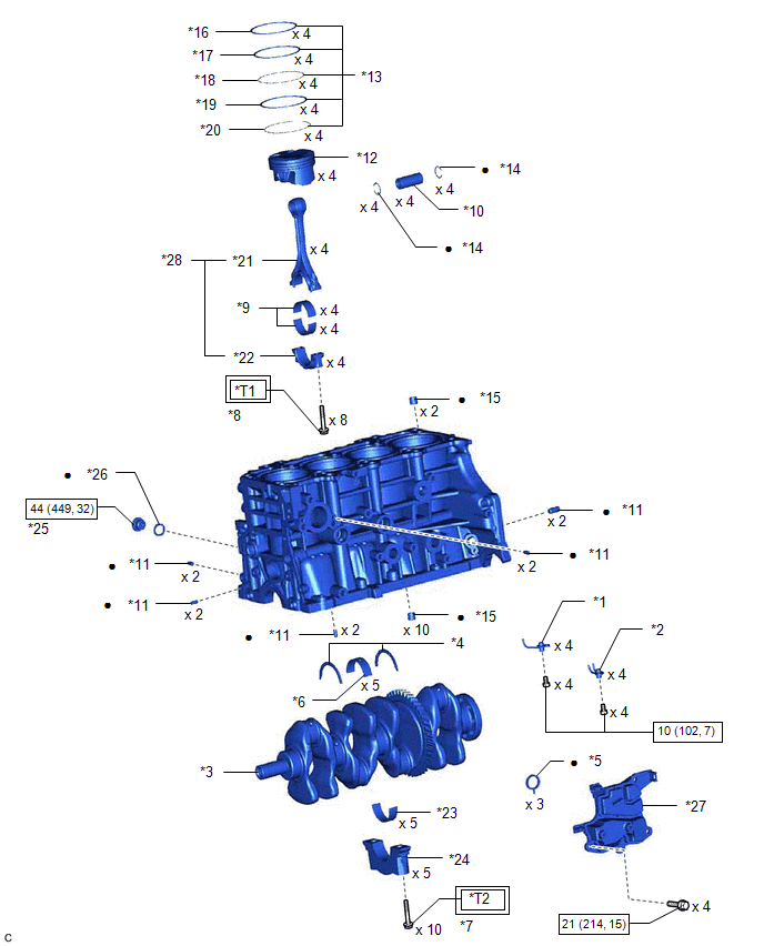
| *1 | NO. 1 OIL NOZZLE SUB-ASSEMBLY | *2 | NO. 2 OIL NOZZLE SUB-ASSEMBLY |
| *3 | CRANKSHAFT | *4 | CRANKSHAFT THRUST WASHER |
| *5 | OIL SEPARATOR GASKET | *6 | CRANKSHAFT BEARING |
| *7 | CRANKSHAFT BEARING CAP SET BOLT | *8 | CONNECTING ROD BOLT |
| *9 | CONNECTING ROD BEARING | *10 | PISTON PIN |
| *11 | STRAIGHT PIN | *12 | PISTON |
| *13 | PISTON RING SET | *14 | PISTON PIN HOLE SNAP RING |
| *15 | RING PIN | *16 | NO. 1 COMPRESSION RING |
| *17 | NO. 2 COMPRESSION RING | *18 | UPPER SIDE RAIL |
| *19 | OIL RING EXPANDER | *20 | LOWER SIDE RAIL |
| *21 | CONNECTING ROD | *22 | CONNECTING ROD CAP |
| *23 | NO. 2 CRANKSHAFT BEARING | *24 | CRANKSHAFT BEARING CAP |
| *25 | NO. 1 STRAIGHT SCREW PLUG | *26 | GASKET |
| *27 | NO. 1 VENTILATION CASE | *28 | CONNECTING ROD SUB-ASSEMBLY |
.png) | Tightening torque for "Major areas involving basic vehicle performance such as moving/turning/stopping": N*m (kgf*cm, ft.*lbf) | .png) | N*m (kgf*cm, ft.*lbf): Specified torque |
| ● | Non-reusable part | - | - |
| *T1 | 1st: 38 (387, 28) 2nd: Turn 90° | *T2 | 1st: 61 (622, 45) 2nd: Turn 90° |
READ NEXT:
 Disassembly
DISASSEMBLY CAUTION / NOTICE / HINT The necessary procedures (adjustment, calibration, initialization, or registration) that must be performed after parts are removed and installed, or replaced during
Inspection
INSPECTION PROCEDURE 1. INSPECT CYLINDER BLOCK FOR WARPAGE (a) Using a precision straightedge and feeler gauge, check the surface which contacts the cylinder head gasket for warpage. Maximum Warpag
Replacement
REPLACEMENT PROCEDURE 1. REPLACE RING PIN NOTICE: It is not necessary to remove the ring pins unless they are being replaced. (a) Remove the 12 ring pins. (b) Using a plastic hammer, install 12 new ri
SEE MORE:
Components
COMPONENTS ILLUSTRATION *1 CENTRAL GATEWAY ECU (NETWORK GATEWAY ECU) *2 ECU INTEGRATION BOX RH *3 GLOVE COMPARTMENT DOOR ASSEMBLY - -
DC/DC Converter Current Sensor Circuit Short to Ground (P0E5111,P0E5115,P0E511F)
DESCRIPTION DTC No. Detection Item DTC Detection Condition Trouble Area MIL Warning Indicate P0E5111 DC/DC Converter Current Sensor Circuit Short to Ground Short to GND detected in reactor current sensor circuit (1 trip detection logic) Inverter with converter assembly Comes
