Lexus ES: Disassembly
DISASSEMBLY
CAUTION / NOTICE / HINT
The necessary procedures (adjustment, calibration, initialization, or registration) that must be performed after parts are removed and installed, or replaced during cylinder block removal/installation are shown below.
Necessary Procedure After Parts Removed/Installed/Replaced| Replaced Part or Performed Procedure | Necessary Procedure | Effect/Inoperative Function when Necessary Procedure not Performed | Link |
|---|---|---|---|
| Auxiliary battery terminal is disconnected/reconnected | Perform steering sensor zero point calibration | Lane control system (for HV Model) | |
| Pre-collision system (for HV Model) | |||
| Parking support brake system (for HV Model)* | |||
| Lighting system (for HV Model) | |||
| Memorize steering angle neutral point | Parking assist monitor system (for HV Model) | | |
| Panoramic view monitor system (for HV Model) | | ||
| Initialize power trunk lid system | Power trunk lid system (for HV Model) | | |
| Replacement of ECM | Perform Vehicle Identification Number (VIN) registration | MIL illuminates | |
| Inspection After Repair |
| |
| Replacement of inverter with converter assembly | Resolver learning |
| |
| Replacement of hybrid vehicle transaxle assembly |
| ||
| Front wheel alignment adjustment |
|
| |
|
|
| |
| Suspension, tires, etc.*1 | Rear television camera assembly optical axis (Back camera position setting) | Parking assist monitor system (for HV Model) | |
| Replacement of front bumper assembly | Front television camera view adjustment | Panoramic view monitor system (for HV Model) | |
| Suspension, tires, etc.*1 |
| ||
| Replacement of headlight ECU sub-assembly LH |
| Lighting system (for HV Model) | |
| Suspension, tires, etc.*1 | Perform headlight ECU sub-assembly LH initialization*2 |
-
*: When performing learning using the Techstream.
Click here
.gif)
- *1: If the vehicle height has changed due to suspension or tire replacement.
- *2: for LED type turn signal light
NOTICE:
- After the power switch is turned off, the radio receiver assembly records various types of memory and settings. As a result, after turning the power switch off, make sure to wait at least 85 seconds before disconnecting the cable from the negative (-) auxiliary battery terminal. (for Audio and Visual System)
- After the power switch is turned off, the radio receiver assembly records various types of memory and settings. As a result, after turning the power switch off, make sure to wait at least 85 seconds before disconnecting the cable from the negative (-) auxiliary battery terminal. (for Navigation System)
PROCEDURE
1. REMOVE NO. 1 VENTILATION CASE
NOTICE:
Perform this procedure only when replacement of the No. 1 ventilation case is necessary.
| (a) Remove the 4 bolts and No. 1 ventilation case from the cylinder block sub-assembly. |
|
.png)
| (b) Remove the 3 oil separator gaskets from the No. 1 ventilation case. |
|
.png)
2. REMOVE NO. 1 STRAIGHT SCREW PLUG
| (a) Using a 10 mm hexagon socket wrench, remove the No. 1 straight screw plug and gasket from the cylinder block sub-assembly. |
|
.png)
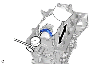
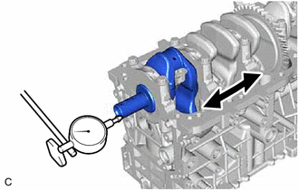
3. INSPECT CONNECTING ROD THRUST CLEARANCE
| (a) Using a dial indicator, measure the thrust clearance while moving the connecting rod sub-assembly back and forth. Standard Thrust Clearance: 0.16 to 0.51 mm (0.00630 to 0.0201 in.) Maximum Thrust Clearance: 0.512 mm (0.0202 in.) HINT: If the thrust clearance is more than the maximum, replace the connecting rod. If necessary, replace the crankshaft. |
|
4. INSPECT CONNECTING ROD OIL CLEARANCE
| (a) Note the alignment marks on the connecting rod and connecting rod cap so that they can be reinstalled to their original locations. |
|
| (b) Using an E12 "TORX" socket wrench, remove the 2 connecting rod bolts and connecting rod cap. HINT: Keep the connecting rod bearing and connecting rod cap together. |
|
.png)
(c) Clean the crank pin and connecting rod bearing.
(d) Check the crank pin and connecting rod bearing for pitting and scratches.
HINT:
If the crank pin or connecting rod bearing is damaged, replace the connecting rod bearings. If necessary, replace the crankshaft.
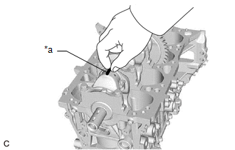
| (e) Lay a strip of Plastigage on the crank pin. |
|
| (f) Check that the front mark of the connecting rod cap is facing the correct direction, and install the connecting rod cap to the connecting rod. |
|
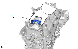
| (g) Apply a light coat of engine oil to the threads and under the heads of the 2 connecting rod bolts. |
|
(h) Using an E12 "TORX" socket wrench, install and alternately tighten the 2 connecting rod bolts in several steps.
Torque:
38 N·m {387 kgf·cm, 28 ft·lbf}
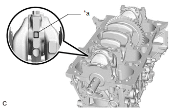
(i) Mark the front of each connecting rod bolt with paint.
.png)
| *a | Paint Mark |
| *b | 90° |
.png) | Front of Engine |
(j) Tighten the connecting rod bolts 90° as shown in the illustration.
NOTICE:
Do not turn the crankshaft during the measurement.
(k) Remove the 2 connecting rod bolts and connecting rod cap.
HINT:
Keep the connecting rod bearing and connecting rod cap together.
| (l) Measure the Plastigage at its widest point. Standard Oil Clearance: 0.027 to 0.059 mm (0.00106 to 0.00232 in.) Maximum Oil Clearance: 0.059 mm (0.00232 in.) HINT:
Standard Connecting Rod Big End Inside Diameter:
Standard Connecting Rod Bearing Center Wall Thickness:
Standard Crank Pin Diameter: 47.992 to 48.000 mm (1.88945 to 1.88976 in.) NOTICE: Remove the Plastigage completely after the measurement. |
|
(m) Perform the inspection above for each cylinder.
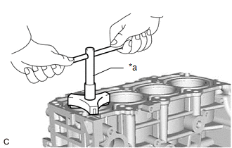
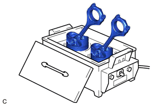
5. REMOVE PISTON WITH CONNECTING ROD
| (a) Using a ridge reamer, remove all the carbon from the top of each cylinder. |
|
(b) Remove the 8 connecting rod bolts, 4 connecting rod caps and 4 connecting rod bearings.
(c) Push the 4 pistons, 4 connecting rods and 4 connecting rod bearings out through the top of the cylinder block sub-assembly.
HINT:
- Keep the connecting rod bearings, connecting rods and connecting rod caps together.
- Arrange the removed parts in such a way that they can be reinstalled to their original locations.
6. REMOVE CONNECTING ROD BEARING
(a) Remove the 8 connecting rod bearings from the 4 connecting rods and 4 connecting rod caps.
HINT:
Arrange the removed parts in such a way that they can be reinstalled to their original locations.
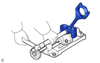
7. INSPECT CRANKSHAFT THRUST CLEARANCE
| (a) Using a dial indicator, measure the crankshaft thrust clearance while prying the crankshaft back and forth with a screwdriver. Standard Thrust Clearance: 0.09 to 0.19 mm (0.00354 to 0.00748 in.) Maximum Thrust Clearance: 0.25 mm (0.00984 in.) HINT: If the thrust clearance is more than the maximum, replace the crankshaft thrust washers as a set. If necessary, replace the crankshaft. Standard Thrust Washer Thickness: 2.43 to 2.48 mm (0.0957 to 0.0976 in.) |
|
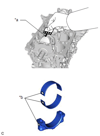
8. REMOVE CRANKSHAFT
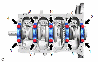
| (a) Uniformly loosen and remove the 10 crankshaft bearing cap set bolts in several steps in the order shown in the illustration. |
|
(b) Remove the 5 crankshaft bearing caps from the cylinder block sub-assembly.
HINT:
- Keep the No. 2 crankshaft bearings and crankshaft bearing caps together.
- Arrange the removed parts in such a way that they can be reinstalled to their original locations.
(c) Remove the crankshaft from the cylinder block sub-assembly.
HINT:
Keep the crankshaft bearings and crankshaft thrust washers together with the cylinder block sub-assembly.
(d) Check each crankshaft journal and crankshaft bearing for pitting and scratches.
If the journal or crankshaft bearing is damaged, replace the crankshaft bearings. If necessary, replace the crankshaft.
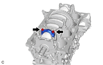
9. REMOVE CRANKSHAFT THRUST WASHER
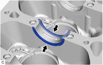
| (a) Remove the 2 crankshaft thrust washers from the No. 3 journal position of the cylinder block sub-assembly. |
|
10. REMOVE CRANKSHAFT BEARING
(a) Remove the 5 crankshaft bearings and 5 No. 2 crankshaft bearings from the cylinder block sub-assembly and 5 crankshaft bearing caps.
HINT:
Arrange the removed parts in such a way that they can be reinstalled to their original locations.
11. REMOVE PISTON RING SET
| (a) Using a piston ring expander, remove the No. 1 compression ring and No. 2 compression ring from the piston. |
|
(b) Remove the oil ring expander, upper side rail and lower side rail from the piston by hand.
HINT:
Arrange the removed parts in such a way that they can be reinstalled to their original locations.
12. REMOVE PISTON PIN HOLE SNAP RING
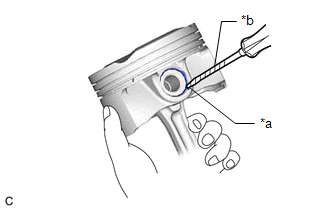
| (a) Using a screwdriver, pry out the 2 piston pin hole snap rings from the piston. HINT: Tape the screwdriver tip before use. |
|
13. REMOVE PISTON
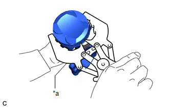
| (a) Gradually heat each piston to between 80 and 90°C (176 and 194°F). CAUTION: Be sure to wear protective gloves. |
|
| (b) Using a brass bar and a hammer, lightly tap out the piston pin and remove the connecting rod. HINT:
|
|
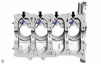
14. REMOVE NO. 1 OIL NOZZLE SUB-ASSEMBLY
| (a) Using a 5 mm hexagon wrench, remove the 4 bolts and 4 No. 1 oil nozzle sub-assemblies from the cylinder block sub-assembly. |
|
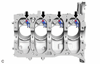
15. REMOVE NO. 2 OIL NOZZLE SUB-ASSEMBLY
| (a) Using a 5 mm hexagon wrench, remove the 4 bolts and 4 No. 2 oil nozzle sub-assemblies from the cylinder block sub-assembly. |
|
READ NEXT:
 Inspection
INSPECTION PROCEDURE 1. INSPECT CYLINDER BLOCK FOR WARPAGE (a) Using a precision straightedge and feeler gauge, check the surface which contacts the cylinder head gasket for warpage. Maximum Warpag
Replacement
REPLACEMENT PROCEDURE 1. REPLACE RING PIN NOTICE: It is not necessary to remove the ring pins unless they are being replaced. (a) Remove the 12 ring pins. (b) Using a plastic hammer, install 12 new ri
Reassembly
REASSEMBLY PROCEDURE 1. INSTALL NO. 2 OIL NOZZLE SUB-ASSEMBLY (a) Using a 5 mm hexagon wrench, install the 4 No. 2 oil nozzle sub-assemblies to the cylinder block sub-assembly with the 4 bolts. Tor
SEE MORE:
Installation
INSTALLATION CAUTION / NOTICE / HINT NOTICE: Make sure to hold the front wiper arm while lifting it, as lifting the front wiper arm by the front wiper blade may damage or deform the front wiper blade. PROCEDURE 1. INSTALL WINDSHIELD WIPER MOTOR ASSEMBLY (a) Using a T30 "TORX" socket wrench, install
Inspection
INSPECTION PROCEDURE 1. INSPECT FRONT NO. 1 SPEAKER ASSEMBLY (a) With the speaker installed, check that there is no looseness or other abnormalities. (b) Check that there is no foreign matter in the speaker, no tears on the speaker cone or other abnormalities. (c) Measure the resistance of the sp
