
Lexus ES: Components
COMPONENTS
ILLUSTRATION
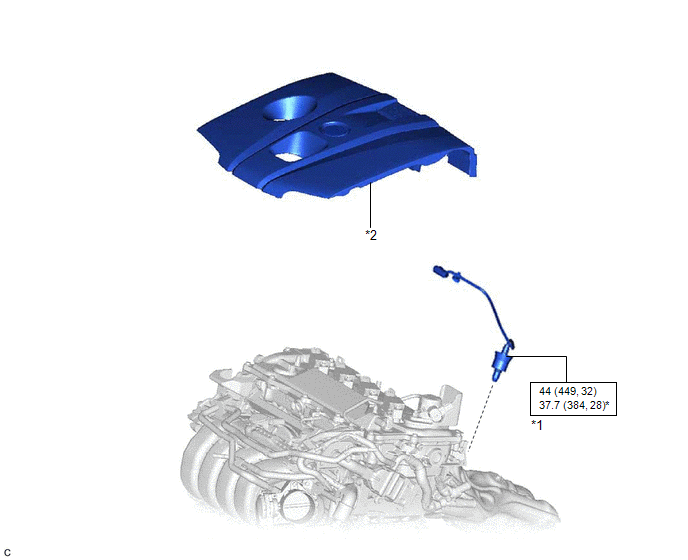
| *1 | AIR FUEL RATIO SENSOR | *2 | NO. 1 ENGINE COVER SUB-ASSEMBLY |
 | N*m (kgf*cm, ft.*lbf): Specified torque | * | For use with SST |
READ NEXT:
 Removal
REMOVAL CAUTION / NOTICE / HINT The necessary procedures (adjustment, calibration, initialization, or registration) that must be performed after parts are removed and installed, or replaced during air
Inspection
INSPECTION PROCEDURE 1. INSPECT AIR FUEL RATIO SENSOR (a) Measure the resistance according to the value(s) in the table below. Standard Resistance: Tester Connection Condition Specified Con
Installation
INSTALLATION PROCEDURE 1. INSTALL AIR FUEL RATIO SENSOR HINT: Perform "Inspection After Repair" after replacing the air fuel ratio sensor. Click here (a) Using SST, install the air fuel ratio
SEE MORE:
Reassembly
REASSEMBLY PROCEDURE 1. INSTALL FUEL PUMP HINT: Perform "Inspection After Repair" after replacing the fuel pump. Click here (a) for Type A: (1) Apply gasoline to a new O-ring. Then install the O-ring and fuel pump spacer to the fuel pump. *1 O-ring *2 Fuel Pump Spacer
Parts Location
PARTS LOCATION ILLUSTRATION *1 OUTER MIRROR SWITCH ASSEMBLY *2 OUTER REAR VIEW MIRROR ASSEMBLY LH *3 OUTER REAR VIEW MIRROR ASSEMBLY RH *4 DEF RELAY *5 OUTER MIRROR LH *6 OUTER MIRROR RH *7 NO. 1 ENGINE ROOM RELAY BLOCK AND NO. 1 JUNCTION BLOCK ASSEMBLY - DEF FUSE
© 2016-2026 Copyright www.lexguide.net
