Lexus ES: Removal
REMOVAL
CAUTION / NOTICE / HINT
The necessary procedures (adjustment, calibration, initialization, or registration) that must be performed after parts are removed and installed, or replaced during air fuel ratio sensor removal/installation are shown below.
Necessary Procedures After Parts Removed/Installed/Replaced| Replaced Part or Performed Procedure | Necessary Procedure | Effect/Inoperative Function when Necessary Procedure not Performed | Link |
|---|---|---|---|
| Inspection after repair |
| |
PROCEDURE
1. REMOVE NO. 1 ENGINE COVER SUB-ASSEMBLY
Click here .gif)
2. REMOVE AIR FUEL RATIO SENSOR
CAUTION:
To prevent burns, do not touch the engine, exhaust manifold or other high temperature components while the engine is hot.
.png)
| (a) Disengage the 3 wire harness clamps. |
|
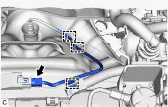
(b) Disconnect the air fuel ratio sensor connector.
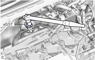
| (c) Using SST, remove the air fuel ratio sensor from the exhaust manifold (TWC: Front Catalyst). SST: 09224-00012 NOTICE: If the air fuel ratio sensor has been struck or dropped, replace it. |
|
READ NEXT:
 Inspection
INSPECTION PROCEDURE 1. INSPECT AIR FUEL RATIO SENSOR (a) Measure the resistance according to the value(s) in the table below. Standard Resistance: Tester Connection Condition Specified Con
Installation
INSTALLATION PROCEDURE 1. INSTALL AIR FUEL RATIO SENSOR HINT: Perform "Inspection After Repair" after replacing the air fuel ratio sensor. Click here (a) Using SST, install the air fuel ratio
SEE MORE:
Components
COMPONENTS ILLUSTRATION *1 FRONT AXLE ASSEMBLY *2 FRONT LOWER BALL JOINT ASSEMBLY *3 COTTER PIN - - Tightening torque for "Major areas involving basic vehicle performance such as moving/turning/stopping": N*m (kgf*cm, ft.*lbf) ● Non-reusable part
Dtc Check / Clear
DTC CHECK / CLEAR CHECK FOR DTCS (a) Connect the Techstream to the DLC3. (b) Turn the power switch on (IG). (c) Turn the Techstream on. (d) Enter the following menus: Powertrain / Hybrid Control / Trouble Codes. Powertrain > Hybrid Control > Trouble Codes (e) Check the DTCs and freeze frame da
