
Lexus ES: Components
COMPONENTS
ILLUSTRATION
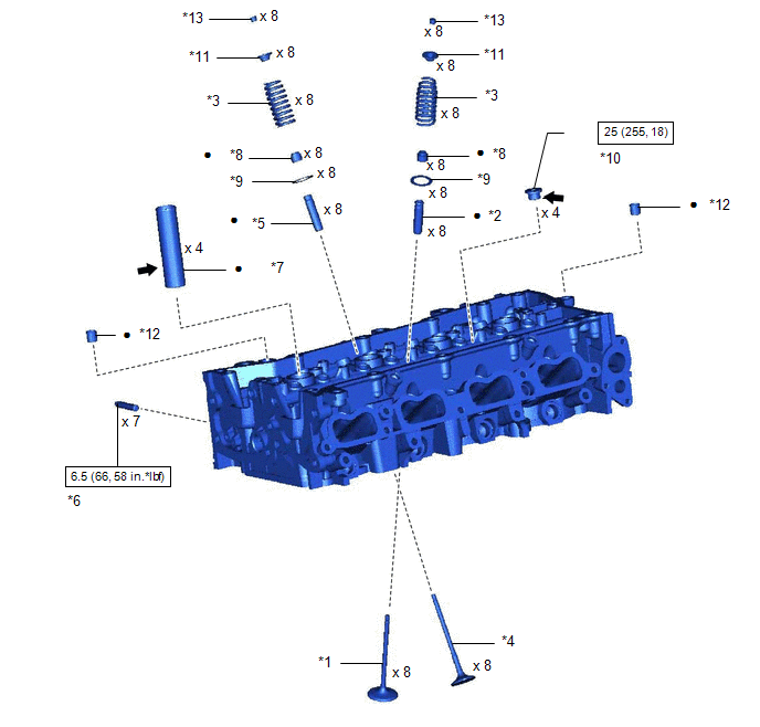
| *1 | INTAKE VALVE | *2 | INTAKE VALVE GUIDE BUSH |
| *3 | COMPRESSION SPRING | *4 | EXHAUST VALVE |
| *5 | EXHAUST VALVE GUIDE BUSH | *6 | STUD BOLT |
| *7 | SPARK PLUG TUBE | *8 | VALVE STEM OIL SEAL |
| *9 | VALVE SPRING SEAT | *10 | NO. 1 STRAIGHT SCREW PLUG |
| *11 | VALVE SPRING RETAINER | *12 | RING PIN |
| *13 | VALVE SPRING RETAINER LOCK | - | - |
.png) | N*m (kgf*cm, ft.*lbf): Specified torque | ● | Non-reusable part |
.png) | Adhesive 1324 | ★ | Precoated part |
READ NEXT:
 Inspection
INSPECTION PROCEDURE 1. INSPECT CYLINDER HEAD SUB-ASSEMBLY (a) Using a precision straightedge and feeler gauge, measure the warpage of the contact surfaces where the cylinder head sub-assembly contact
Replacement
REPLACEMENT PROCEDURE 1. REPLACE INTAKE VALVE GUIDE BUSH (a) Heat the cylinder head sub-assembly to between 80 and 100°C (176 and 212°F). (b) Place the cylinder head sub-assembly on wooden blocks. C
Reassembly
REASSEMBLY PROCEDURE 1. INSTALL SPARK PLUG TUBE HINT: When using a new cylinder head sub-assembly, the spark plug tubes must be replaced. (a) Apply adhesive to a new spark plug tube as shown in the
SEE MORE:
Installation
INSTALLATION PROCEDURE 1. INSTALL FUEL PRESSURE SENSOR (FUEL DELIVERY PIPE WITH SENSOR ASSEMBLY) HINT: Perform "Inspection After Repair" after replacing the fuel pressure sensor (fuel delivery pipe with sensor assembly). Click here Click here NOTICE:
Do not remove the fuel pressure sensor fr
Illumination for Panel Switch does not Come on with Tail Switch ON
CAUTION / NOTICE / HINT NOTICE:
Depending on the parts that are replaced during vehicle inspection or maintenance, performing initialization, registration or calibration may be needed. Refer to Precaution for Navigation System.
Click here
When replacing the radio receiver assembly, always re
© 2016-2026 Copyright www.lexguide.net
