Lexus ES: Components
COMPONENTS
ILLUSTRATION
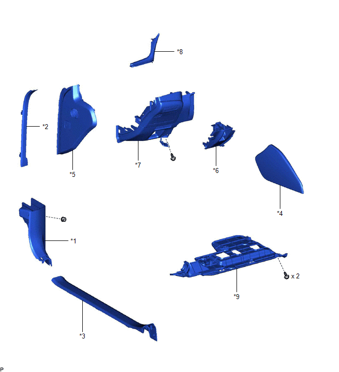
| *1 | COWL SIDE TRIM BOARD LH | *2 | FRONT DOOR OPENING TRIM COVER LH |
| *3 | FRONT DOOR SCUFF PLATE LH | *4 | INSTRUMENT PANEL FINISH PANEL END LH |
| *5 | INSTRUMENT SIDE PANEL LH | *6 | LOWER INSTRUMENT PANEL |
| *7 | LOWER INSTRUMENT PANEL FINISH PANEL SUB-ASSEMBLY | *8 | NO. 1 INSTRUMENT CLUSTER MOULDING |
| *9 | NO. 1 INSTRUMENT PANEL UNDER COVER SUB-ASSEMBLY | - | - |
ILLUSTRATION
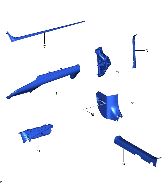
| *1 | AIR CONDITIONING CONTROL ASSEMBLY | *2 | COWL SIDE TRIM BOARD RH |
| *3 | FRONT DOOR OPENING TRIM COVER RH | *4 | FRONT DOOR SCUFF PLATE RH |
| *5 | INSTRUMENT SIDE PANEL RH | *6 | LOWER INSTRUMENT PANEL SUB-ASSEMBLY |
| *7 | NO. 2 INSTRUMENT CLUSTER MOULDING | - | - |
ILLUSTRATION
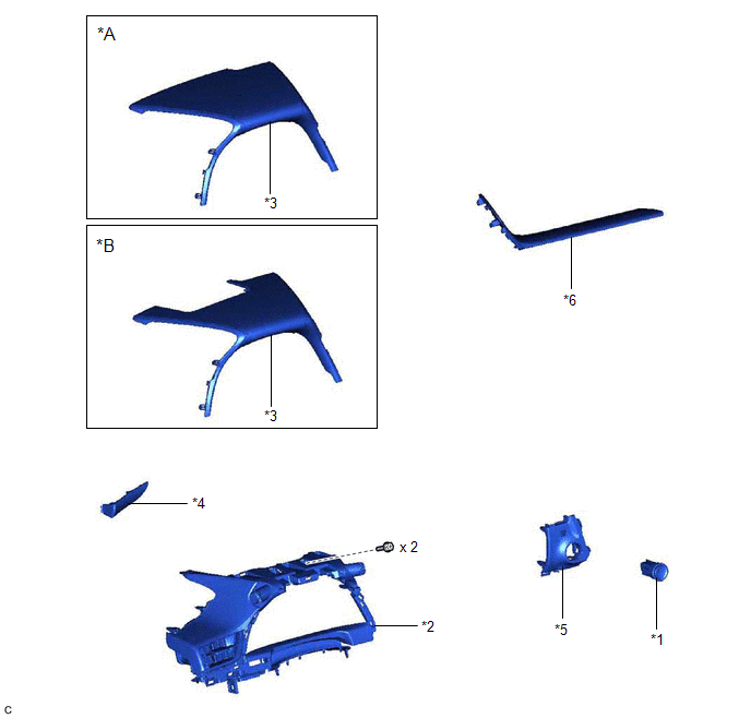
| *A | w/o Headup Display | *B | w/ Headup Display |
| *1 | ENGINE SWITCH | *2 | INSTRUMENT CLUSTER FINISH PANEL ASSEMBLY |
| *3 | INSTRUMENT CLUSTER FINISH PANEL SUB-ASSEMBLY | *4 | NO. 1 INSTRUMENT CLUSTER FINISH PANEL GARNISH |
| *5 | SWITCH BASE | *6 | UPPER INSTRUMENT PANEL FINISH PANEL SUB-ASSEMBLY |
READ NEXT:
 Removal
REMOVAL PROCEDURE 1. REMOVE FRONT DOOR SCUFF PLATE LH Click here 2. REMOVE COWL SIDE TRIM BOARD LH Click here 3. REMOVE FRONT DOOR OPENING TRIM COVER LH Click here 4. REMOVE INSTRUMENT SIDE PANE
Inspection
INSPECTION PROCEDURE 1. INSPECT ENGINE SWITCH (a) Check the resistance. (1) Measure the resistance according to the value(s) in the table below. Standard Resistance: Tester Connection Conditi
Installation
INSTALLATION PROCEDURE 1. INSTALL ENGINE SWITCH (a) Attach the claw to install the engine switch as shown in the illustration. Install in this Direction 2. INSTALL SWITCH BASE Click here 3
SEE MORE:
Problem Symptoms Table
PROBLEM SYMPTOMS TABLE HINT:
Use the table below to help determine the cause of problem symptoms. If multiple suspected areas are listed, the potential causes of the symptoms are listed in order of probability in the "Suspected Area" column of the table. Check each symptom by checking the suspect
Parts Location
PARTS LOCATION ILLUSTRATION *1 ECM *2 NO. 1 ENGINE ROOM RELAY BLOCK AND NO. 1 JUNCTION BLOCK ASSEMBLY - INJ FUSE *3 IGNITION COIL ASSEMBLY *4 SPARK PLUG
